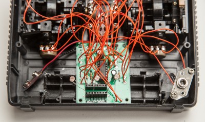
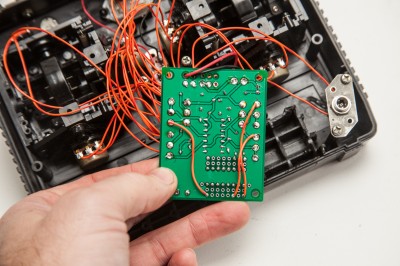
The NAND Synth PCB has a mini breadboard section on it to facilitate modification. Recently while building our Radio NAND we took a couple pictures to help get the ideas flowing on mods for the NAND Synth.
If you look at the schematic for the NAND Synth you’ll notice the potentiometers are are all wired in a rheostat configuration. This means it’s really easy to put other potentiometers in series with them. This could be to narrow the range, set a floor or a ceiling. So we got a little crazy and instead of adding a regular potentiometer we added some optical resistors in series with the potentiometers. Optical resistor function as potentiometers, the more or less light the receive, the more or less resistance they have. So, we created a light based or light sensitive NAND Synth. We’re calling it the Radio NAND because we put it inside a Futaba RC controller. Crazy, huh?
First off we put a couple headers in the breadboard area. The headers aren’t necessary but if you want to play around with fixed resistor values or do other experiments we’d highly recommend them. If you don’t have headers you can use an IC socket too. Disconnect pin 3 of the pots from the PCB and resolder the wire to one of the pads inline on one side of the breadboard area of the NAND Synth PCB. On the other side of the breadboard area run a wire back to the pin 3 location of the pot on the PCB. Now any resistor or resistor like component you put across the breadboard will be additional resistance to the potentiometer and change the effects of the NAND Synth.
If this is confusing to you, check the pictures below, they should help. And remember, lots of things act like resistors. Have fun!


super cool, just did it. more fun to control with movement than knobs
thanks!!!
making a gift for a little one