


Super Power 2 Assembly
Thank you for purchasing the Synthrotek Super Power 2 – Eurorack Power Supply Kit. This is an intermediate build. If you feel like you can handle it, please proceed! If not, get some help from a friend with experience or purchase a fully completed unit.
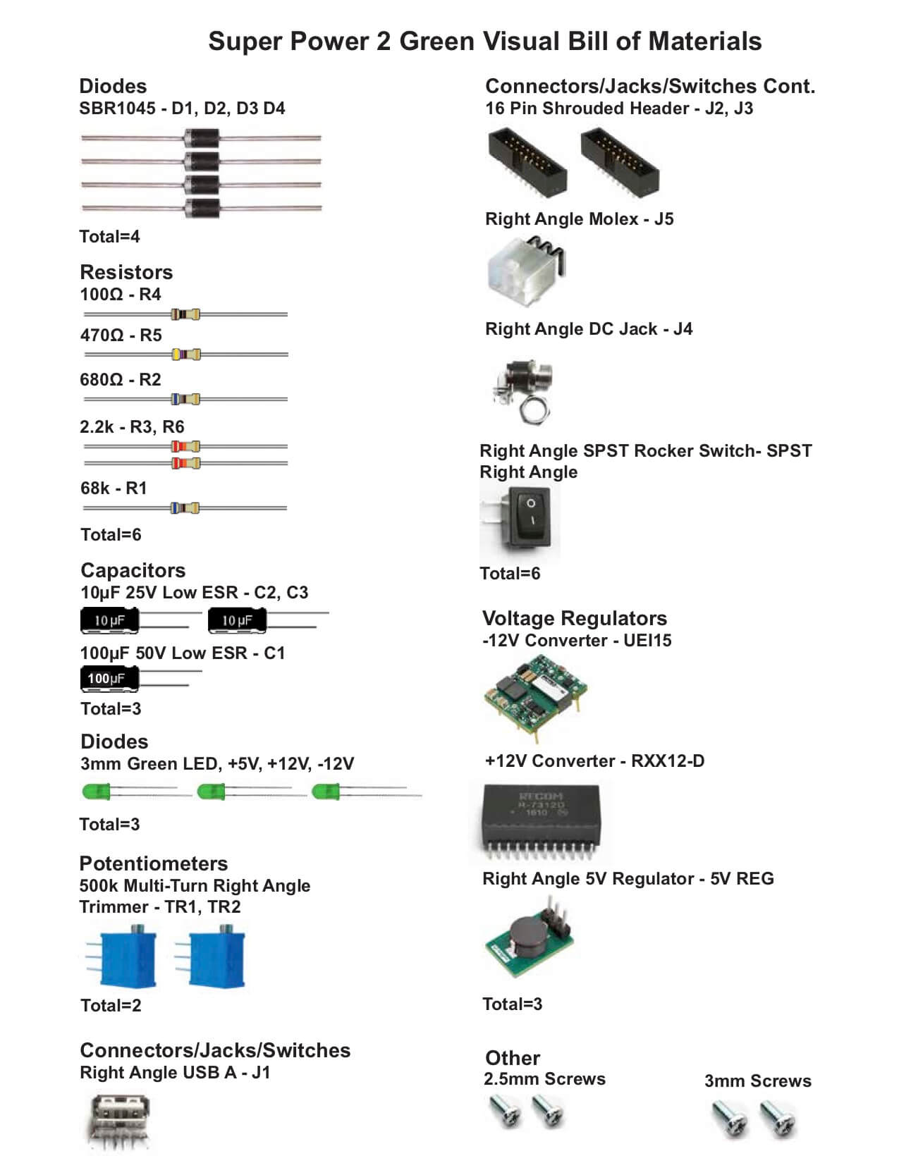
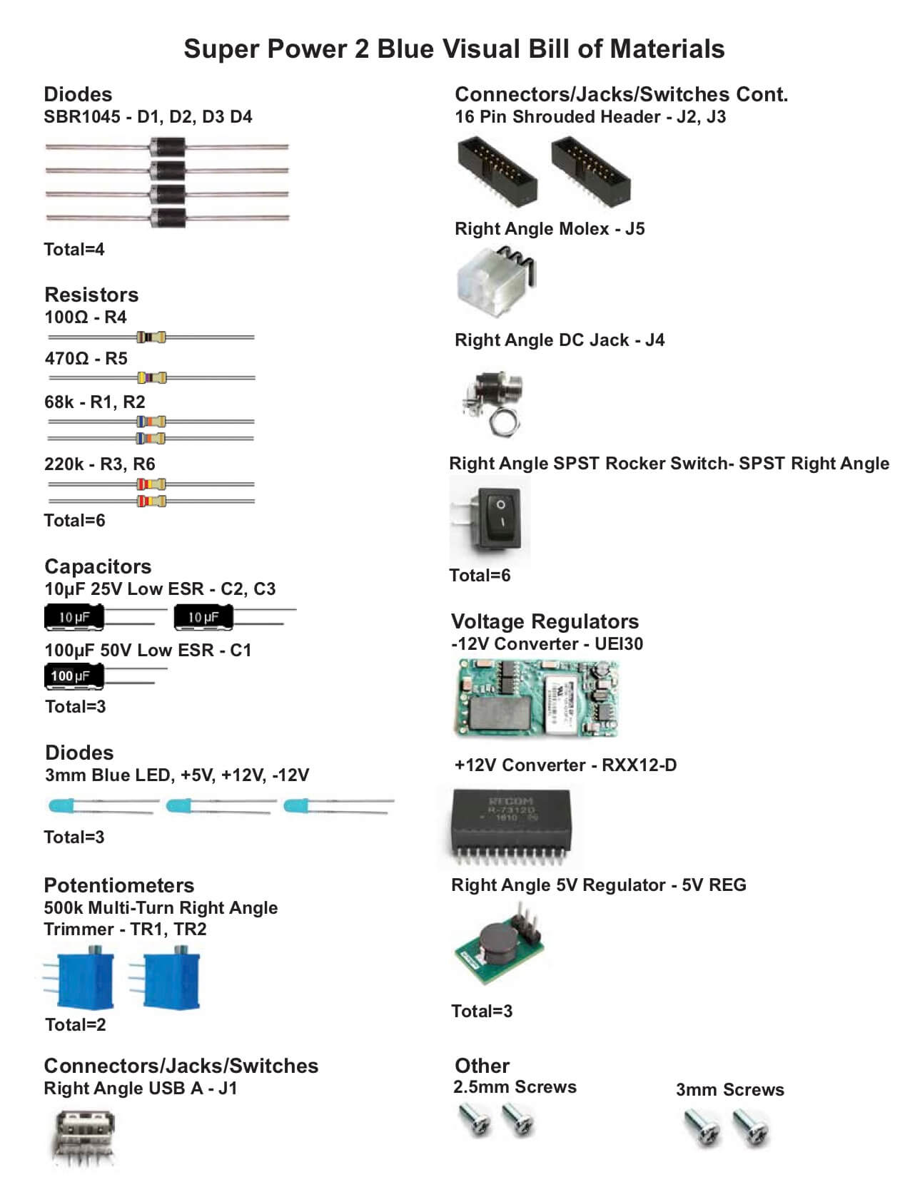
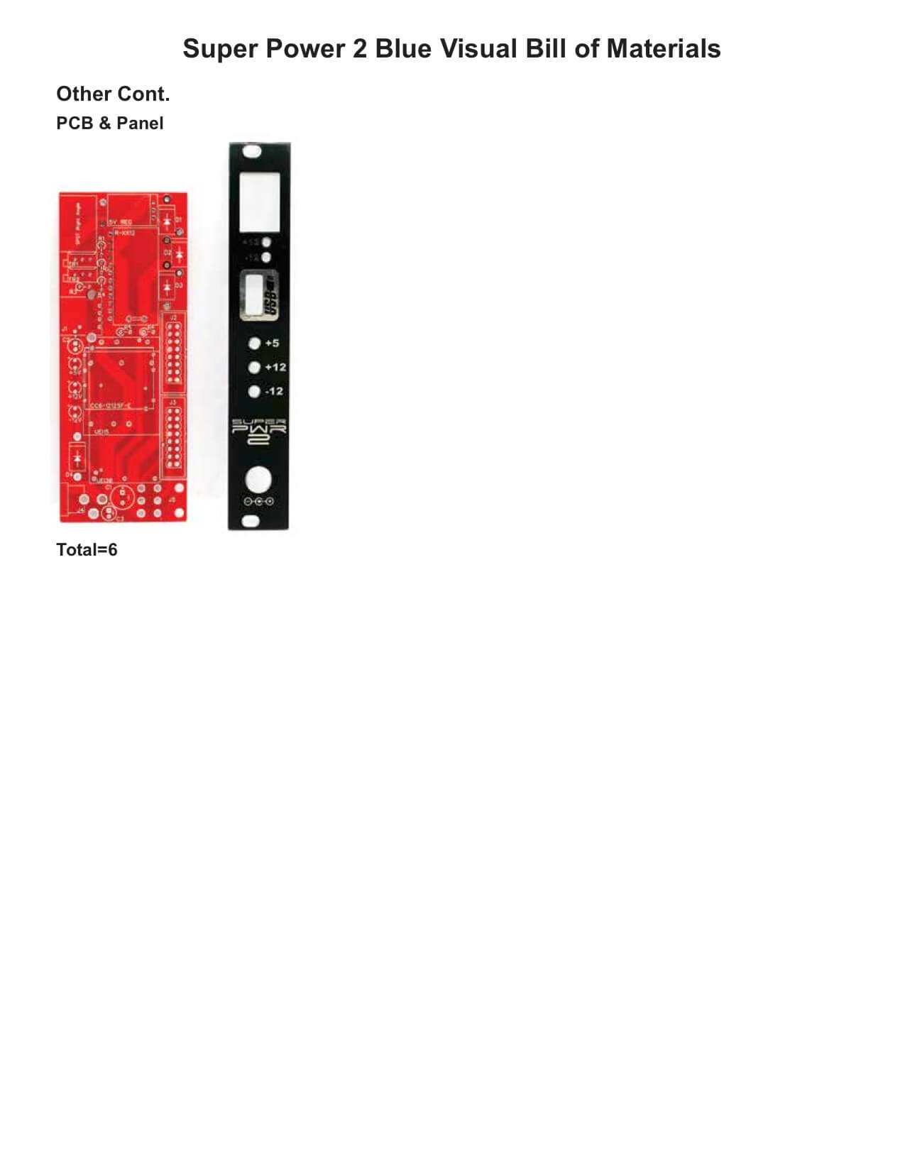
Please build according to the BOM, and not these instructions or the pictures alone. Some components may have changed since these were written, or we may not be able to get the exact components in the pictures. These instructions show the Super Power Blue converters; the Red and Green versions will have different converters.
For a BOM with Mouser part numbers, click here.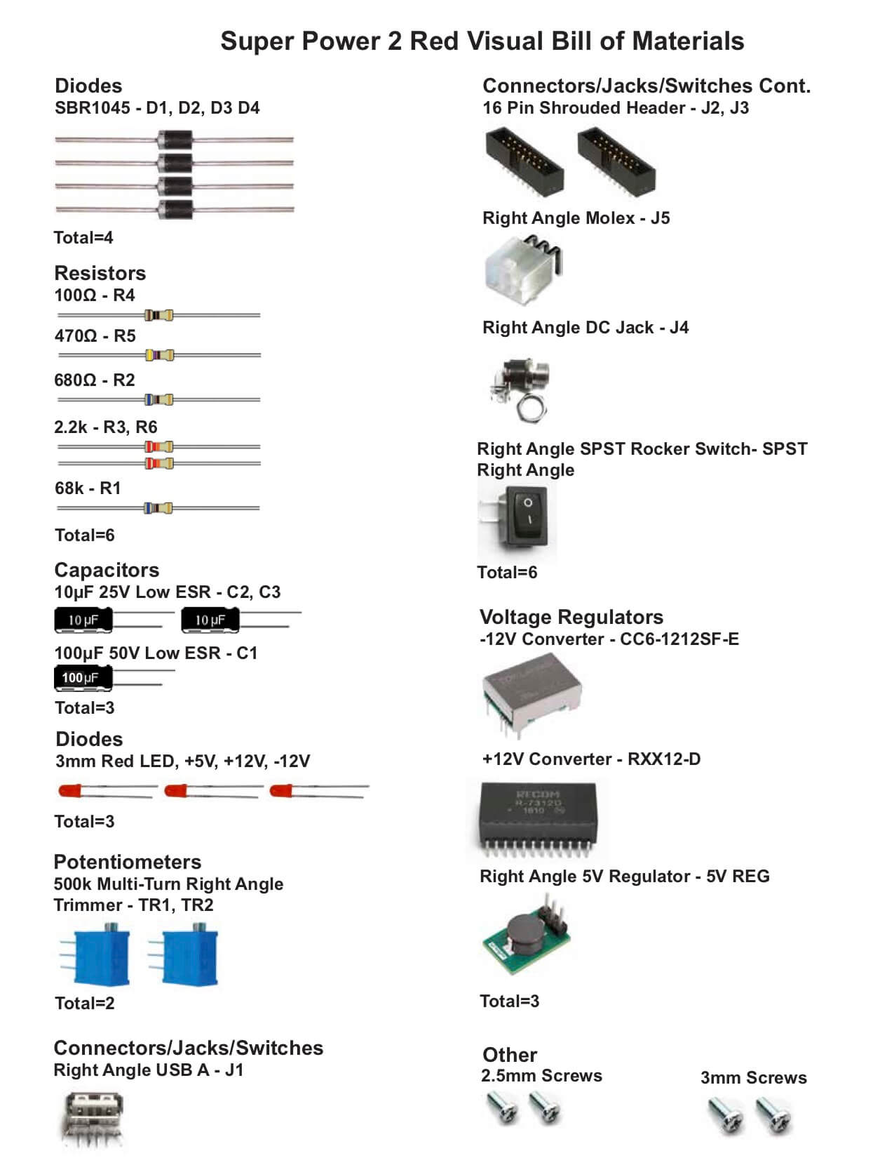

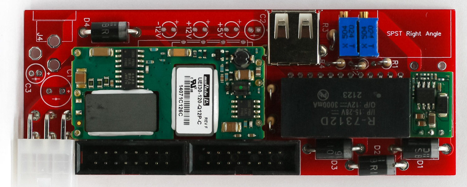
DIODES
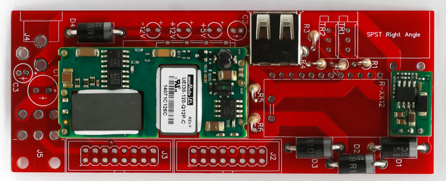
First thing we are going to populate is the diodes. Following the BOM, insert all the diodes into their proper spots, paying attention to the polarity. Diodes are polarized components, and must be populated correctly to function. Make sure to align the cathode stripe on the diode with the cathode marking on the silkscreen.
Then you can flip your project over onto a flat surface and solder all the diodes in place. Then clip the excess leads.
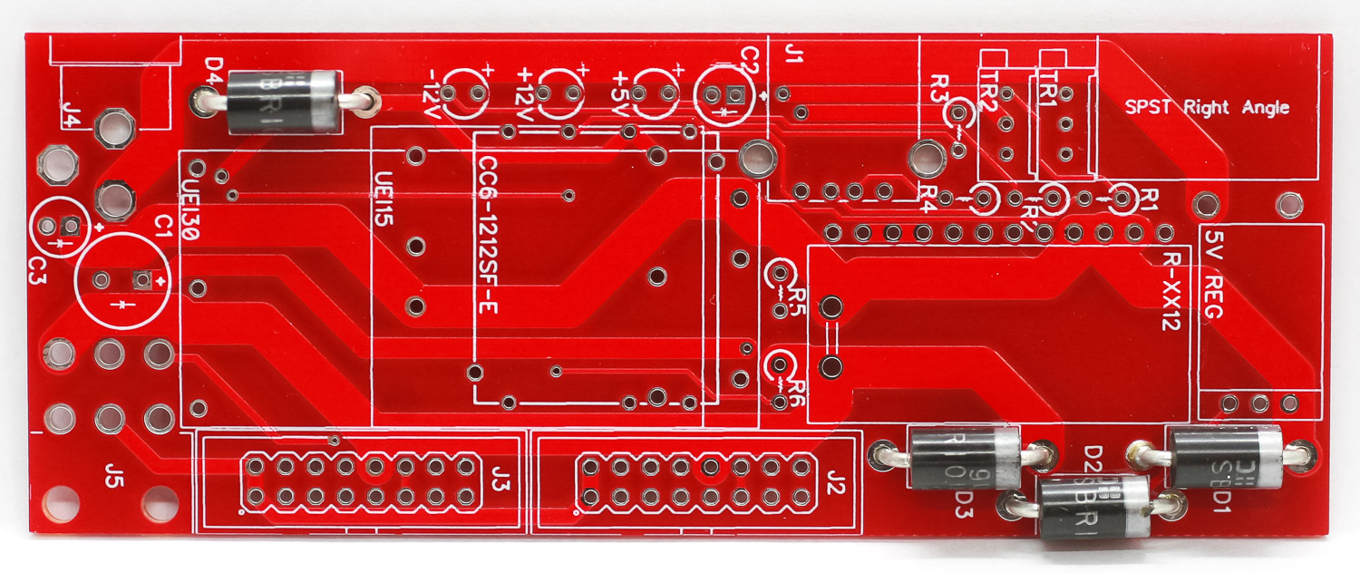
Super Power 2 Diodes
5V CONVERTER
Place the 5V Converter into the PCB as shown below, carefully turn over and solder in place.
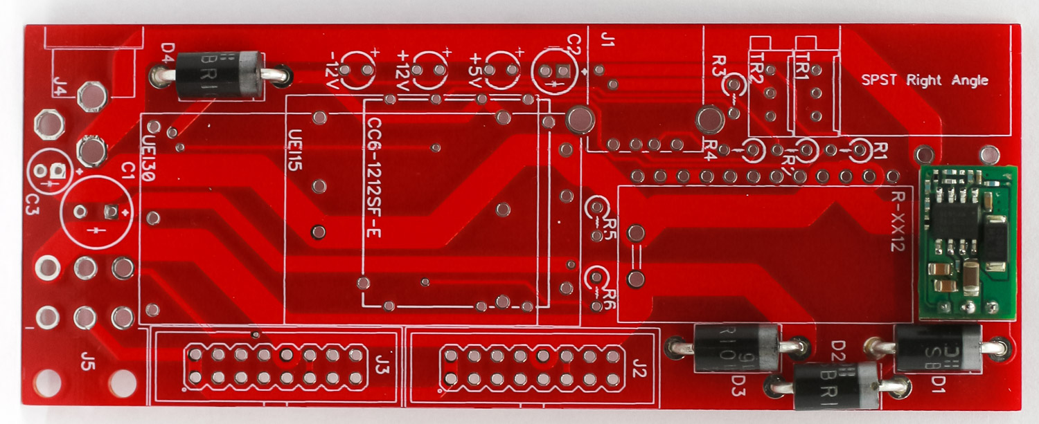
Super Power 2 5V Converter
-12 VOLT CONVERTER
Place the -12V Converter (there are three different options, so yours may look different) into the PCB and carefully turn over and solder in place. Trim excess leads.
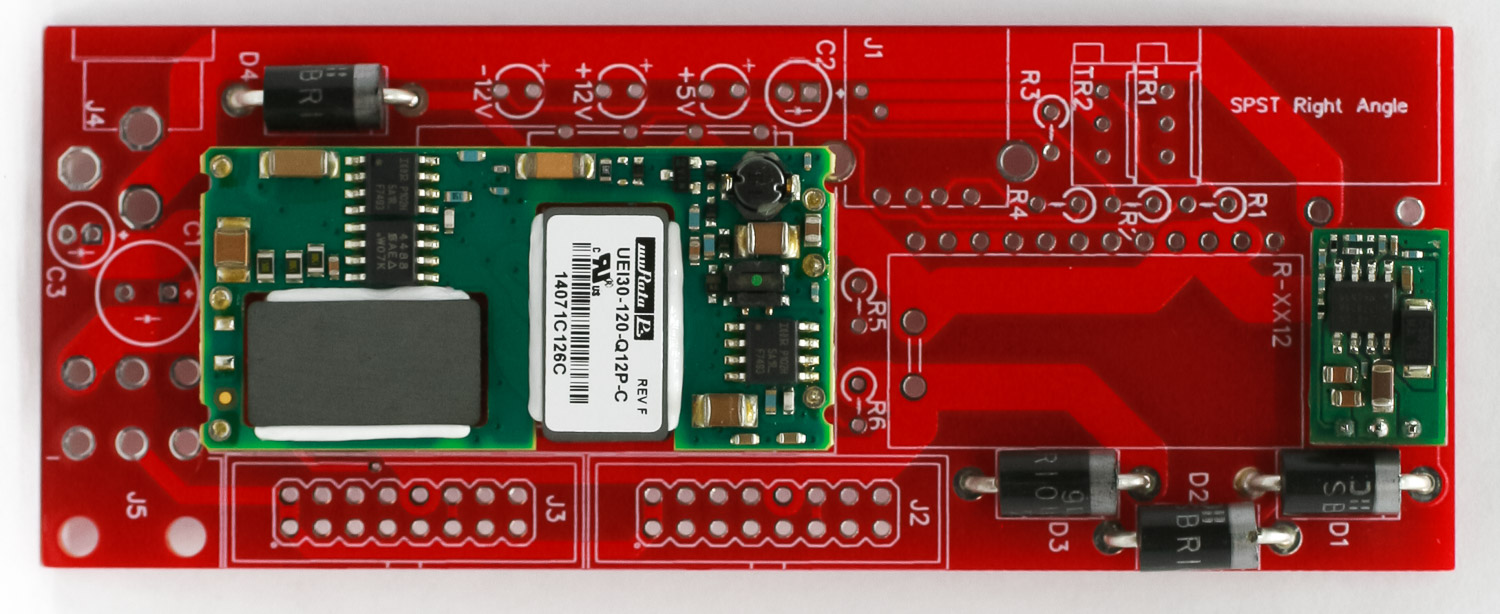
-12V Converter
USB JACK
Place the USB jack into the PCB as shown below, carefully turn over and solder in place.
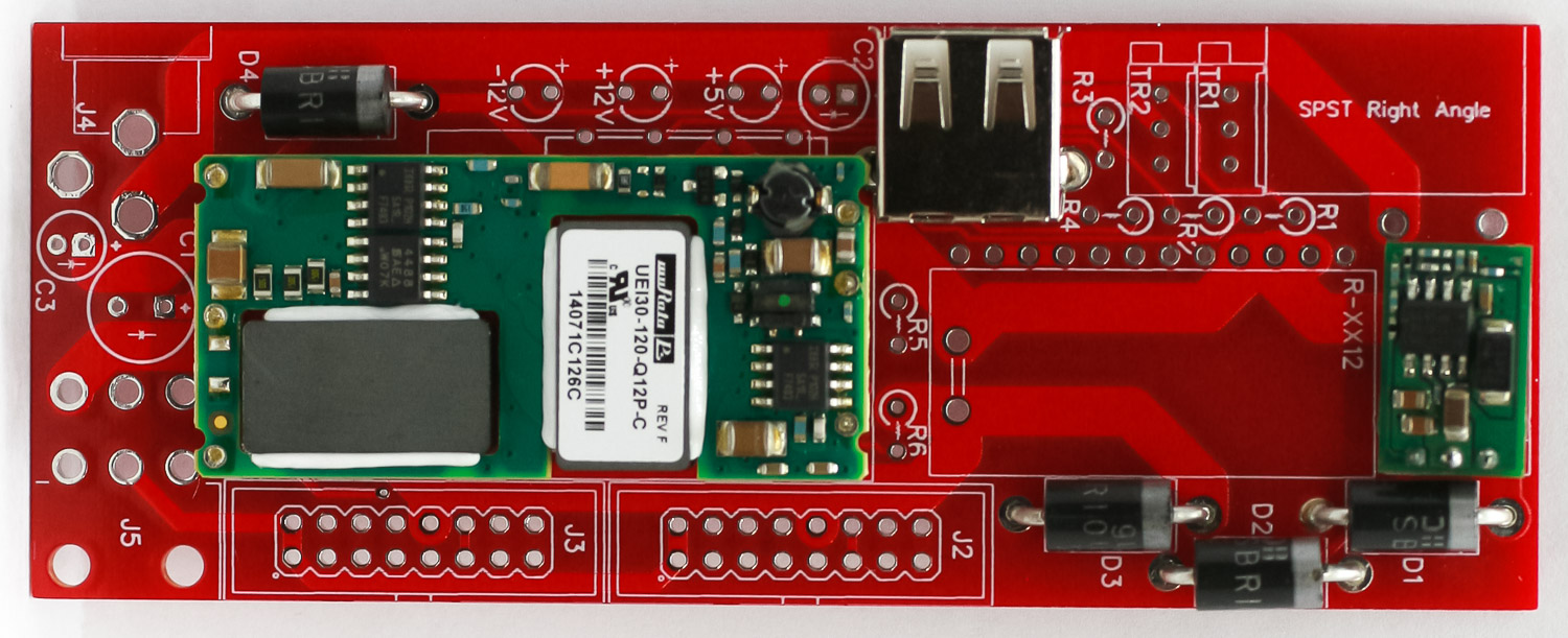
Super Power 2 USB Jack
RESISTORS
Next, pre-bend the stand-up resistors, place them into the PCB, carefully turn the PCB over and trim excess leads.
Super Power 2 Resistors
16-Pin Power Headers
Place and solder in the two 16-pin power headers by aligning the notch on the header with the notch on the PCB silk screen.
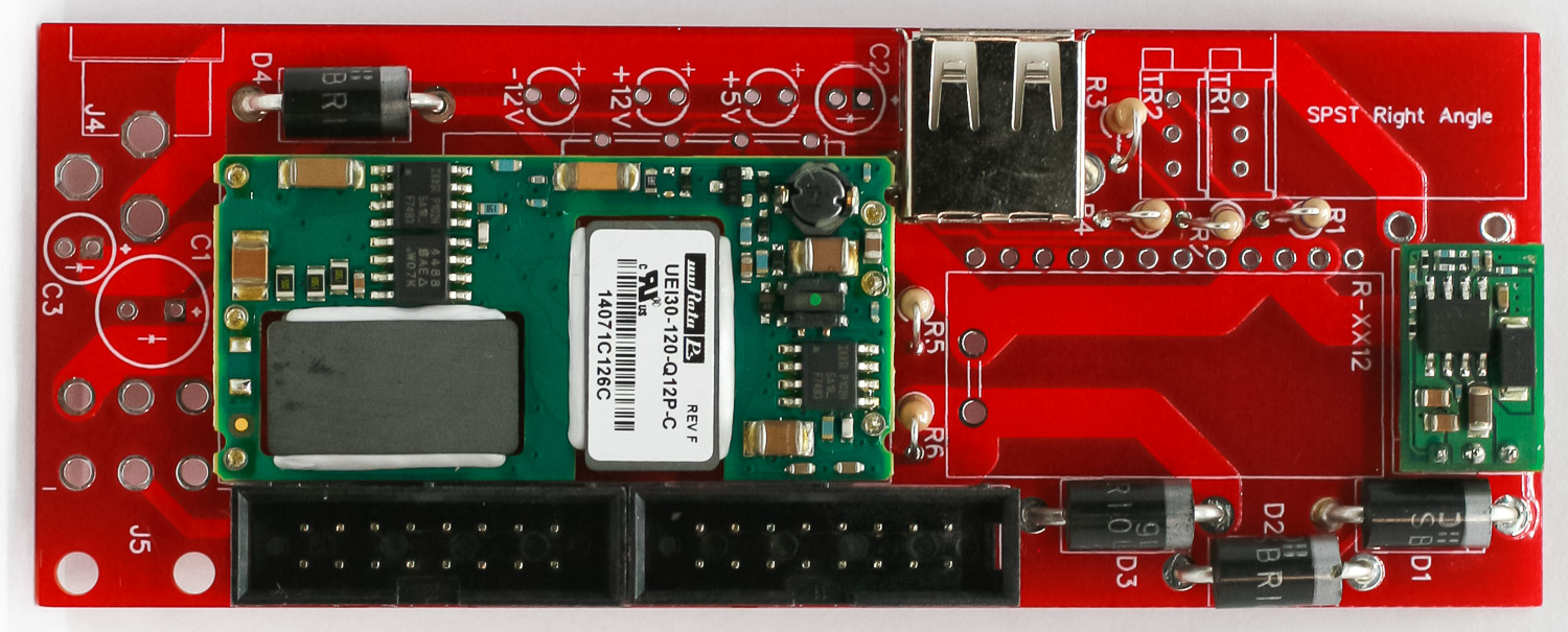
Super Power 2 Power Headers
+12 Voltage Regulator
Place and solder the +12 voltage regulator as shown below.
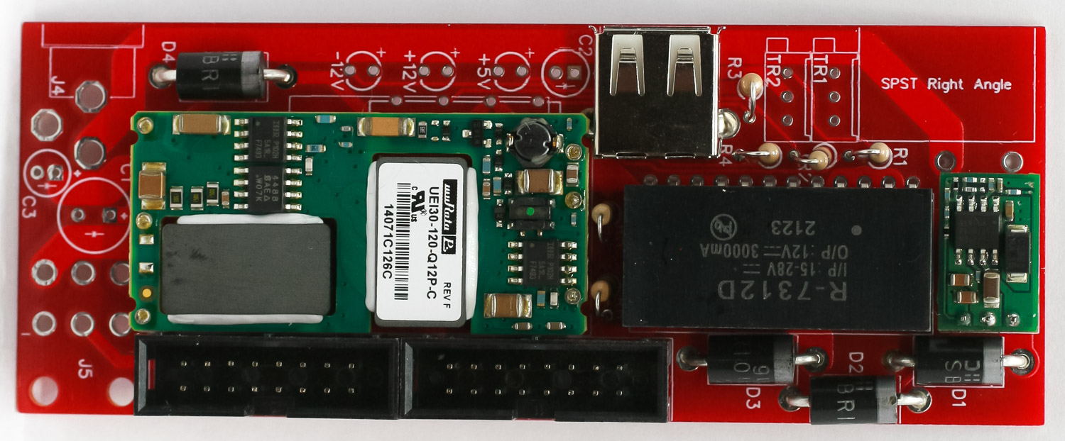
Super Power 2 +12V Converter
Trim Pots
Place and solder the two trim pots as shown below.
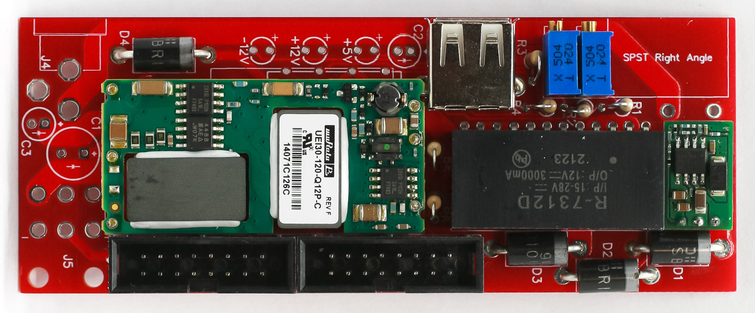
Super Power 2 – Multi Turn Pots
Molex Connector
Place and solder the Molex connector as shown below. Trim excess leads.
Super Power 2 Molex Connector
Electrolytic Caps and Panel Assembly.
First place and solder the electrolytic capacitors in the PCB by aligning the longer lead with the pad that has the “+” mark on in. Carefully turn over and trim excess leads.
Next, place the rocker switch into the panel. If you are having trouble squeezing it into the panel, take a pair of pliers and apply pressure to the retaining clips first, it will make it easier to push through. Then add the DC Jack to the PCB (don’t solder yet). Join the panel to the PCB by inserting the switch leads into the PCB; tighten the DC jack nut on the jack (this will hold the panel in place loosely). VERY CAREFULLY turn the project over and solder the DC jack and switch into place by keeping the PCB 90 degrees from the panel. TAKE YOUR TIME!
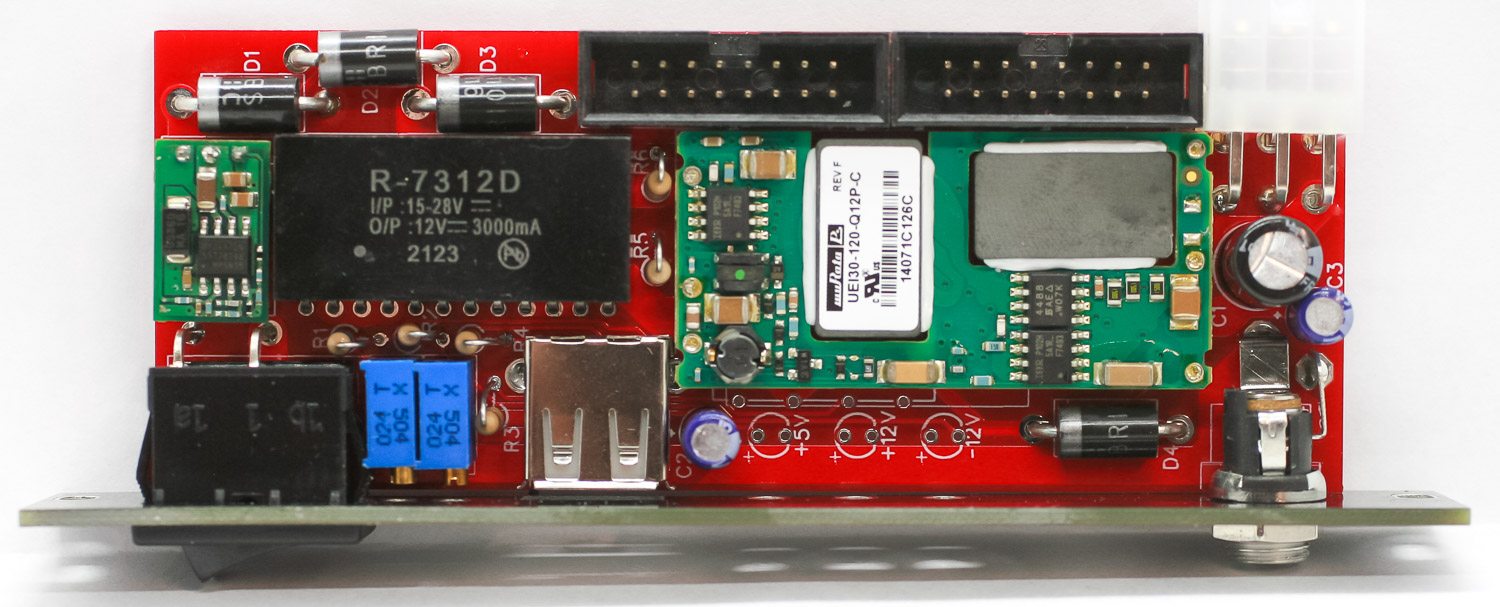
Super Power 2 Caps and Panel
Panel LEDs
Pre-bend the LEDs so that the longer lead can be placed into the hole that has the “+” near it (its the top). Carefully place in the project, turn over to solder. Clip excess leads.
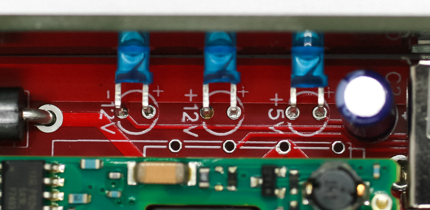
Super Power 2 LEDs
Final Project
You are now ready to test your module!
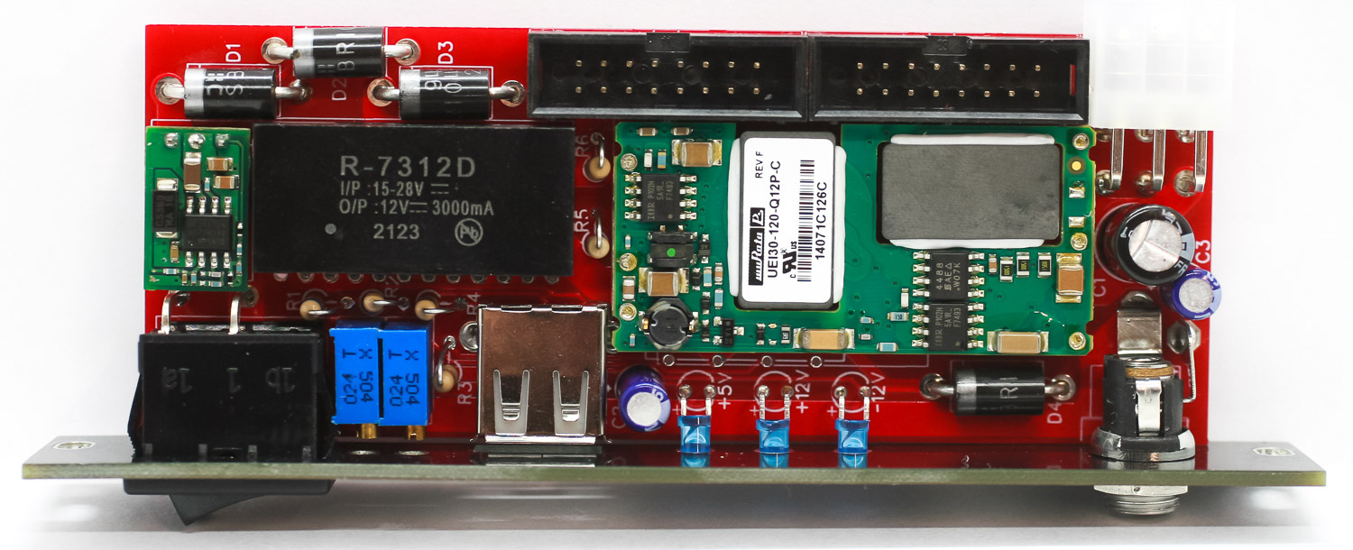
Super Power 2 Final Project
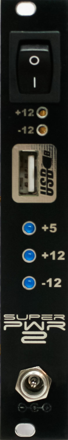
Super Power 2 – Final Build