


Important Links
Product Page
Store Page
Assembly Instructions
Bill of Materials
Capacitor and Resistor Lookup Guide
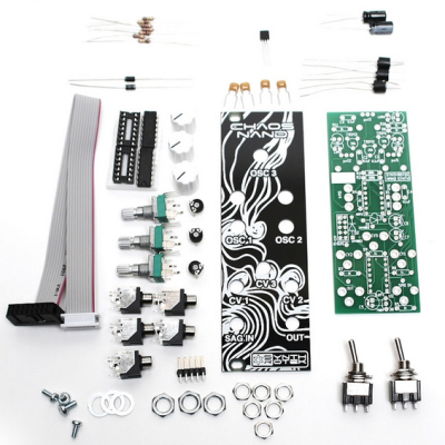
Welcome to the Eurorack version of our Chaos Nand Eurorack Version. Please follow the instructions in order to make assembly easier. There are some tricky mechanical parts, so go slowly and read everything before attacking this project. Also please do not refer to the photos alone! Follow the BOM and our capacitor and resistor look up guides as the color of some components can change. We update the BOM with the most up-to-date values, which will result in the best sounding product by our standards. Lets Begin!
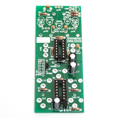
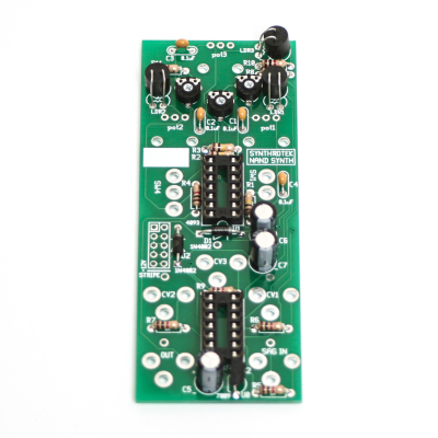
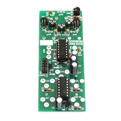
BOM Layout
Eurorack Chaos Nand BOM
If you’ve received your parts and ready to build, the first thing you should do is to check to make sure you have all the parts. Check your kit against the Eurorack NAND BOM. If you’re missing anything we’ll send it to you free of charge.
Soldering the Components
Attention: Changes may occur after the Assembly Instructions are created and the photos may not reflect those changes. Always use the BOM to verify the placement of components.
Resistors and Diodes
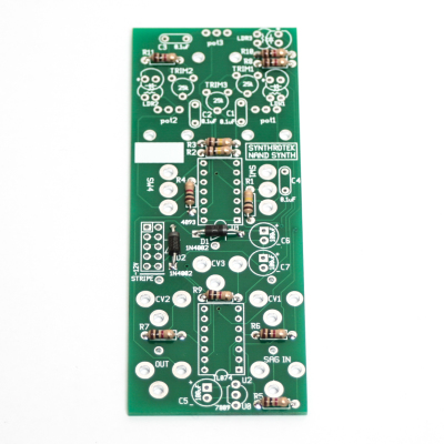
Chaos Nand Resistors and Diodes
First solder all the resistors and diodes into place. Ensure that the line on the diode matches with the line on the PCB silkscreen. Resistors are not polar sensitive so you may install them in any orientation.
IC Sockets
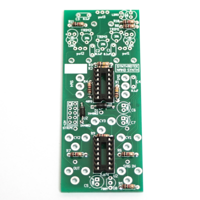
Chaos Nand IC Sockets
Next, Place the 2 IC sockets into place by aligning the notch on the sockets with the notch on the PCB silk Screen. Turn over and solder in place.
Ceramic Capacitors
Chaos Nand Ceramic Capacitors
Now populate and solder in place the Ceramic Capacitors. These are not polarized, so you can place them in either way. Trim leads after soldering.
Electrolytic Capacitors
Chaos Nand Electrolytic Capacitors
The electrolytic capacitors C5, C6, and C7 are polar sensitive. Make sure that the longest lead from the electrolytic capacitor goes into the hole marked with the plus (+) sign. Solder and Trim.
Voltage Regulator, Vactrols and Trim Pots
Chaos Nand Vactrols and Voltage Regulator
Now let’s install the voltage regulator. You need to align the flat side of the voltage regulator to the image of the flat side on the PCB silkscreen.
NSL-7053 Vactrols
On the black cylinder of the vactrol is a small dot. Make sure that the dot is aligned right next to the marking on the silkscreen.
VTL5C3 Vactrols
There is a small “+” sign on the side of the vactrol that needs to be oriented on the OPPOSITE side of the dot on the PCB. Look for the red + in the picture below for the proper alignment. The vactrols will sit up above the resistors a bit.
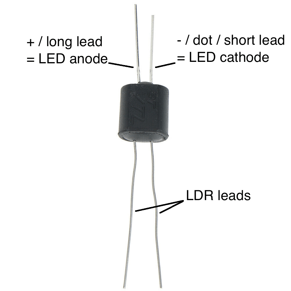
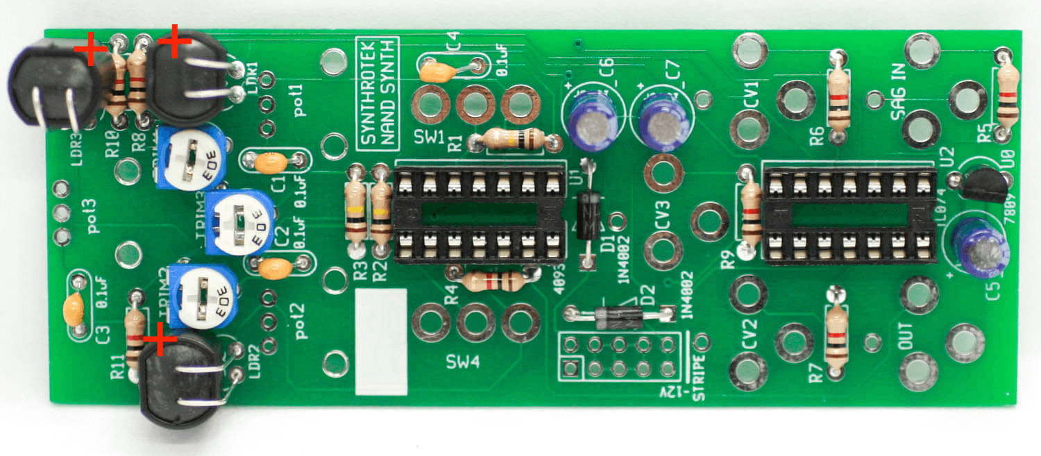
Align the + on the VTL5C3 vactrols with the red plus signs in the picture
ICs and Power Header Pins
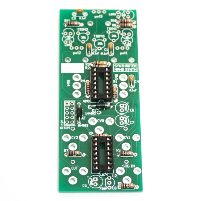
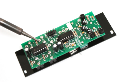
Chaos Nand ICs and Power Header
Now install the 10-pin header as shown above and solder on the other side of the PCB. Next CAREFULLY (as to not bend the pins) install the ICs into the headers by aligning the notch in the ICs with the notch on the headers and PCB silk screen.
Potentiometers & Jacks
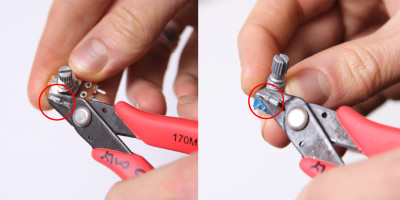
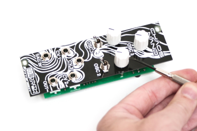
First, trim the placement metal nubs off the pots to ensure that the panel fits flush.
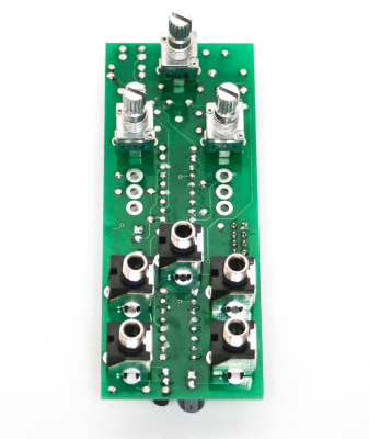
Chaos Nand Jacks and Pots
To finish the circuit we will need to flip the PCB and install the jacks and the pots to the other side of the PCB. To ensure that the panel mounts flush: DO NOT SOLDER THE JACKS OR POTS JUST YET! JUST PLACE THEM INTO POSITION AS SHOWN ABOVE
Switches
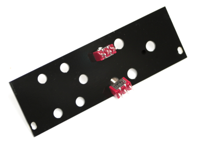
Switches to Panel Mounting
Threading Switch Nuts
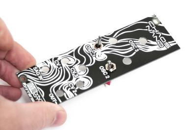
Without Soldering any of the jacks, pots or switches yet, take your 2 toggle switches and slightly thread them onto the panel as shown above.
Place Panel Over PCB
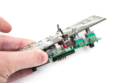
Next, place the panel over the project and proceed to tighten (not too hard!) all of the nuts for the jacks, pots and switches. This will keep the panel straight and inline with the PCB.
Add remainder nuts
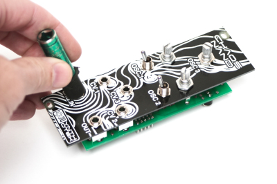
NOW! You can turn the project over and solder the jacks, pots and switches to the PCB.
Soldering Jacks, Nuts and Switches
Completed Unit
Adding Knobs
Congrats! You are now done and your unit is ready for testing! Install into your Eurorack case and make some noise! Have fun!
Calibrating and Testing Procedures
—-TESTING CONTROLS—-
Set all 3 OSC knobs fully counter clockwise, and set both OSC switches to the DOWN position on the Modular Chaos NAND. When you monitor the output, you should hear a square wave that can be anywhere around A#3 (230Hz).
Slowly turn the OSC 3 knob clockwise and you should notice the pitch rising up past 20kHz. Now set the OSC 3 knob fully counter clockwise.
Set the OSC 1 switch to the UP position (turning on Oscillator 1). The pitch should be anywhere around 45Hz (between F1 and F#1). Slowly turn the OSC 1 knob clockwise and you should notice the pitch rising up past 20kHz. Now set the OSC 1 knob fully counter clockwise and set the OSC 1 switch to the DOWN position.
Set the OSC 2 switch to the UP position (turning on Oscillator 2). The pitch will be pretty low, somewhere around 60Hz. Slowly turn the OSC 2 knob clockwise and you should notice the pitch rising all the way up until somewhere around 10kHz (it might be hard to tell as OSC 3’s audio is constantly going) it will drop in pitch when the OSC 2 knob is set fully clockwise. Now set the OSC 2 knob fully counter clockwise and set the OSC 2 switch to the DOWN position.
—-CALIBRATING CV INPUTS —-
Each CV INPUT needs to be calibrated before use via a trimpot on the back of the Modular Chaos NAND. The trimpots set the amount of influence that each CV INPUT has on each oscillator. Each CV INPUT is vactrol based and NOT 1V/Oct. They will only respond to Unipolar (0-10V+) voltages. Here is how the CV INPUTS correlate to the trimpots:
CV 1 = TRIM1 = OSC 1
CV 2 = TRIM2 = OSC 2
CV 3 = TRIM3 = OSC 3
Take a 10V+ Envelope, Gate, or an Offset and plug it into the CV 3 INPUT. Turn TRIM3 almost fully counter clockwise until the frequency goes just out of audible range when the CV INPUT signal is at 10V+.
Set the OSC 1 switch to the UP position. Take a 10V+ Envelope, Gate, or an Offset and plug it into the CV 1 INPUT. Turn TRIM1 almost fully counter clockwise until the frequency goes just out of audible range when the CV INPUT signal is at 10V+. Set the OSC 1 switch to the DOWN position.
Set the OSC 2 switch to the UP position. Take a 10V+ Envelope, Gate, or an Offset and plug it into the CV 2 INPUT. Turn TRIM2 almost fully counter clockwise until the frequency goes as high as it can when the CV INPUT signal is at 10V+. Set the OSC 2 switch to the DOWN position.
By now you should be able to confirm that the Modular Chaos NAND is working correctly.
We love to hear back from our customers about how they’re putting our products to use! If you run into any issues, please consult our TROUBLESHOOTING GUIDE.
25 Comments