Important Links
Product Page
Store Page
Manual
Assembly Instructions
QC/Testing Instructions
Bill of Materials
Capacitor & Resistor Lookup Guide
Thank you for purchasing the Synthrotek FOLD kit! This is an intermediate build. There are a lot of parts and some tight soldering at the transistor and voltage regulator pads. A fine solder tip is recommended. It is very important to get all the components properly soldered into the PCB in the correct placement. If you feel like you can handle it, please proceed! If not, get some help from a friend with experience or purchase a fully completed unit.
Please build according to the BOM, and not these instructions or the pictures alone. Some components may have changed since these were written, or we may not be able to get the exact looking components in the pictures.
These instructions are for version 2.1 and 2.2. The only thing that is different is that version 2.2 has an extra trimmer resistor which is useful in calibrating the ring modulator section.
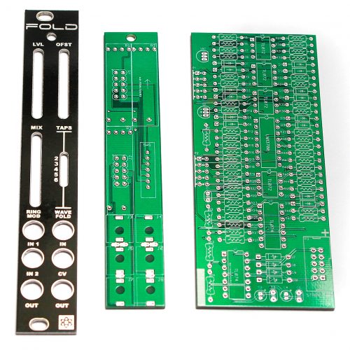
Logic Board Diodes
The diodes are polarized, so make sure to populate them with the cathode stripe in the same direction as indicated by the silkscreen.
Once everything is in place, carefully flip your project over, and solder the components in place. Clip any excess leads on the bottom of the board.
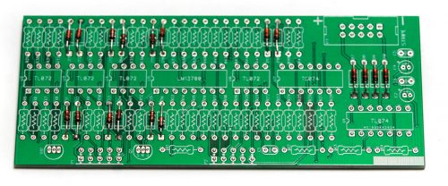
Resistors
Populate the resistors on the logic board. Resistors are non polarized, so it doesn’t matter which direction you put them on the PCB, but it will help with any troubleshooting that may arise if you line up all the tolerance bands (usually a gold stripe) on one side. This will make it easier to read the color codes on the resistors.
Once everything is in place, carefully flip your project over, and solder the components in place. Clip any excess leads on the bottom of the board.
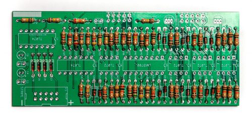
Version 2.2 Trimmer Resistor
Populate the trimmer resistor as shown below. Carefully turnover to solder in place.
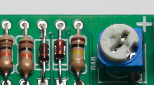
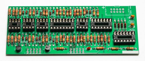
IC Sockets, Transistor and Voltage Regulator
Next up are the IC sockets. Take care when populating these to not bend any of the legs, and to line up the notch in the end with the same notch that is displayed on the silkscreen. This notch indicates where pin 1 of the IC is. When you have them populated, carefully flip your project over and solder everything in place.
A trick to getting these nice and flat is to only solder one or two pins of each socket, and then reflow the solder joint while gently pushing on the top of the socket to seat it flat against the PCB. Then continue on and solder the rest of the pins.
Next up is the transistor and the 9v regulator. These are both polarized, so make sure when populating them that you align the flat edge of the component with the corresponding flat line on the silkscreen. Also pay close attention to the number on the side of the component, as it is very easy to mix up the voltage regulator with the transistors, as they look alike. Be careful when soldering these in place that none of the legs create a solder bridge!
Once everything is in its proper place according to the BOM, carefully flip your project over and solder everything in place, clipping any excess leads on the bottom. The transistor and voltage regulator pads are very close together! Please take extra time here to not make any solder bridges! One way to combat this is to solder one leg, then clip it, and then solder another and clip it, etc. A fine solder tip makes this much easier.
Ceramic Capacitors
Now we can populate the three ceramic capacitors. These are non-polarized and can be inserted either direction. If the capacitor coating runs down the legs a little, make sure the coating doesn’t poke into the pads. Once they are in, carefully flip over your project and solder them in place, clipping the excess leads.
Electrolytic Capacitors, 10 Pin Power Header and IC’s
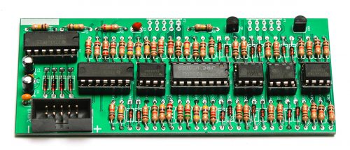
The electrolytic capacitors are polarized, so take care! Ensure that the longer leg (the leg that is further from the stripe indicator on the body) goes through the solder pad with the little ‘+’ symbol next to it.
Once it is aligned properly, carefully flip your project over and solder it in place, clipping the excess leads on the bottom.
Next up is the shrouded power header. Make sure when populating this that the notch in the header is lined up with the notch designation in the silkscreen (it’s on the side closest to the edge of the PCB).
When you’re sure that it is oriented correctly, carefully flip your project over and solder it in place. Use the same trick as the IC sockets to get it nice and flush with the PCB.
Finally, insert the ICs into their sockets. You will need to bend the legs inward a little to make them fit. Match up the notch on the IC’s with the notch on the socket and PCB silkscreen. Make sure that all the legs are firmly seated in the socket.
Control Board
Board to Board Headers
We are now going to start building the control board. We will start with the 5×2 right angle board to board headers. Make sure when you populate these that the side of the header without the bend in it goes through the control board. The black plastic stopper should be resting against the board.(see image below)
Make sure that you get these seated nice and flat against the board to ensure that everything will fit behind the front panel, and be at a nice 90 degree angle to the control board.

It is HIGHLY recommended to solder only one of the middle pins of these headers first, then re-flow the solder and re-seat the header so it sits nice and flat. Take your time with these and make sure everything is straight and flat before soldering the rest of the pins in place.
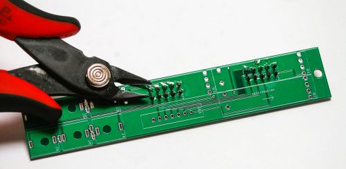
Once they are all soldered in place, we need to clip the pins that we just soldered down a little bit so that they don’t interfere with the slide potentiometers that need to go over them.
After clipping it is highly recommended to re-flow all the solder joints on these guys, just to make sure that there aren’t any cold solder joints on these. These pads will be inaccessible after completing the build.
Slide Potentiometers, Jacks, Switch and Hex Standoff
First populate the aluminum hex standoff. You can do so by inserting a metal-finish 2.5mm screw through the bottom of the board, and then spinning the hex standoff a little to get it started. Then use a Phillips head screwdriver to gently tighten the assembly together.
Next up are the slide potentiometers, jacks and switch. The pots will only fit in the PCB one way, but the legs can get a little bent during shipping or general handling, so take your time and make sure they all get fitted properly into their respective solder pads.
The five-position switch can go in either way.
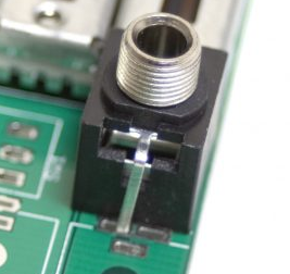
Four of the six jacks have ground pins that are facing each other and need to be slightly bent over in order to fit (see photo above). Since these are ground pins, it’s ok if they are touching.
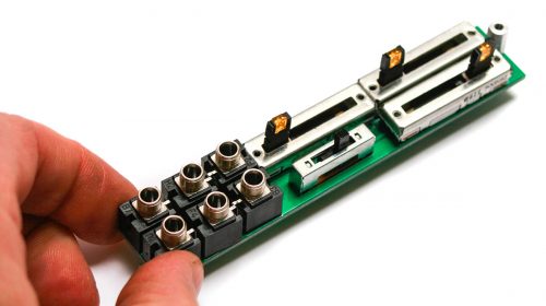
Once everything is in place (but not soldered!), carefully set the front panel down over everything.
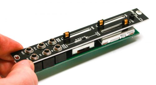
Next, grab your favorite tool (pliers not recommended!) and tighten down the nuts on the jacks (just barely!). If you are using a socket, tape the end of the socket so that you don’t scratch the panel.
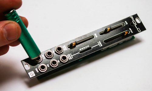
Then insert the black Allen head screw through the front panel and tighten it down on the standoff.
Now you can turn the board over (carefully) and solder the legs in place. Take care not to create a solder bridge between the slide pots near the standoff hole, they are very close together. You will need to prop up the switch from the front in order to push the legs through.
Final Board Mating
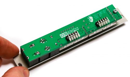
When mating the two boards, take care to make sure that everything lines up at a 90 degree angle. We can use the same trick as before with the headers on the control board to make sure that the logic board is sitting as flush to the bent part of the headers, and is coming straight off the control board. Solder just one pin of the header, and then re-heat and straighten until you are satisfied with how it looks.
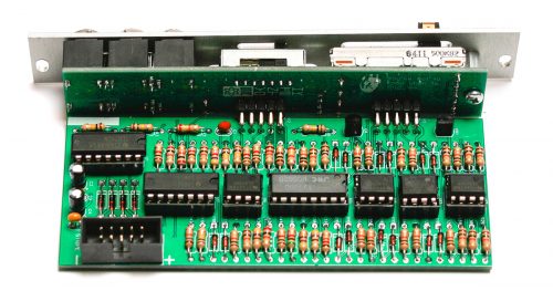
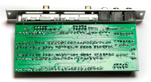
After you are happy with how it looks, solder the remaining pins, and then take your trusty clippers and clip the excess off the bottom of the pins so they don’t bump into another module when installed in your system.
QC Instructions
Let’s make sure it’s working correctly.
Tools you will need:
- A Eurorack system with a sine or triangle wave oscillator, a second audio signal and a CV source.
- An oscilloscope and buffered mult (optional, but helpful)
With your Eurorack system powered off, plug the FOLD into your eurorack power via the included 10 to 16 pin power cable. All three LEDs on the pots should light up.
Ring Mod Calibration
If you are building FOLD v2.2 you can calibrate your module using the trimmer pot on the PCB marked R48. To do this, patch an audio signal into Ring Mod input 1 and do not patch anything into Ring Mod input 2. Next, trim R48 until there is as little audio coming out of the Ring Mod output as possible. You can check this by ear, or better yet with a scope.
The ring mod circuit only uses the three bottom left jacks; none of the other jacks or controls apply to it.
- Patch two separate audio signals into IN 1 and IN 2.
- Patch the output into a mixer; the two signals should combine together. Some frequency combinations will sound better than others, so mess around with it a bit!
Wave Folder
General functionality:
- Slide all the pots down to 0%.
- Plug a sine or triangle wave into WAVE FOLD IN jack.
- If using an oscilloscope: patch the right-side (wave folding side) OUT into a buffered mult input, and patch the outputs of the mult into your o-scope and output/line level mixer.
- With the MIX pot at 0%, you should have a dry signal. On the o-scope, you should see a normal triangle or sine wave.
- Slide the MIX pot to 100%. Your amplitude should flatline or come close to this. There should be little or no audible signal.
LVL:
- The LVL increases the amplitude of the effected waveform or the waveform to be folded until it folds. This pot will not function unless the MIX pot is above 0%.
LVL on Oscilloscope:
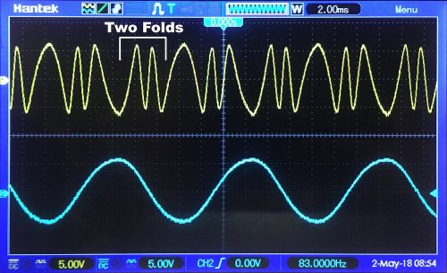
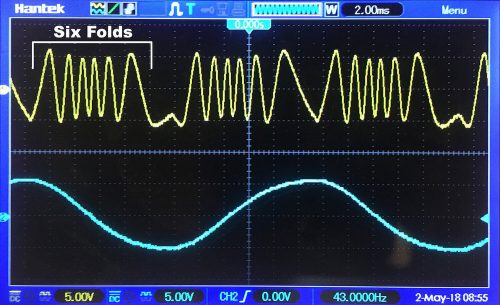
- Note: the blue waveform in the pictures below is the original waveform.
- Set the TAPS to 2. Move the MIX to 100% and OFST to 30%. Slide the LVL pot upward; on the oscilloscope, you should see two full folds around 40-50% of the pot range:
- Set the TAPS to 6. Leave the MIX and OFST pots where they are. Slide the LVL pot near 100%; on the oscilloscope, you should see six folds:
- Note: After it folds to the set amount of taps, the amplitude will continue to rise until the waveform clips. Moving the LVL higher and the OFST to either extreme can create clipping, as in the image below:
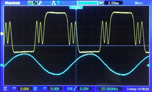
- The CV input responds to both positive and negative voltage. Plug a positive CV source into the CV jack and move the LVL pot to 0%. When the LVL pot is at 0%, 0V to +5V will emulate the full travel of the pot. When the LVL pot is at 100%, 0V to -5V will emulate the full travel of the pot down to 0%.
- Slide the LVL pot to 100%. The positive voltage will push past the limits of the LVL pot. Unpatch the CV input; the LVL should audibly change back to its normal 100%.
OFST:
- The OFST pot controls the offset. This pot will not function unless both the MIX and LVL pots are above 0%. It can’t be used to offset the dry signal alone.
- The OFST pot can adjust the folded wave up or down to help achieve the desired timbre and wave symmetry and can make folded waves clip. Adjust to taste.
Completed Unit
Congratulations on your completed FOLD module! Go make some music!


