


Important Links
Store Page
Assembly Instructions
Bill of Materials
Schematic
Capacitor and Resistor Lookup Guide
Optical Theremin Assembly Instructions
Welcome to the Optical Theremin Assembly Instructions! If you’re new to circuit-building, this is a great kit because it’s easy to build and it makes some crazy sounds. Let’s get started!
BOM Layout

Match your kit with this picture to make sure you have all the parts.
If any components are missing, please let us know!
Assembly
Attention: Changes may occur after the Assembly Instructions are created and the photos may not reflect those changes. Always use the BOM to verify the placement of components.
IC Socket, Capacitors, and Resistors

Solder in the IC socket. Line up the half-moon notch with the notch on the PCB.
C1 and C2 are .1uF ceramic capacitors. R2 is a 1M resistor.
Ceramic capacitors and resistors are non-polar so don’t worry about negative or positive leads.
Power Supplies

Black is negative, Red is positive

Wire up the DC jack as shown. P=Pin S=Sleeve C=Connect
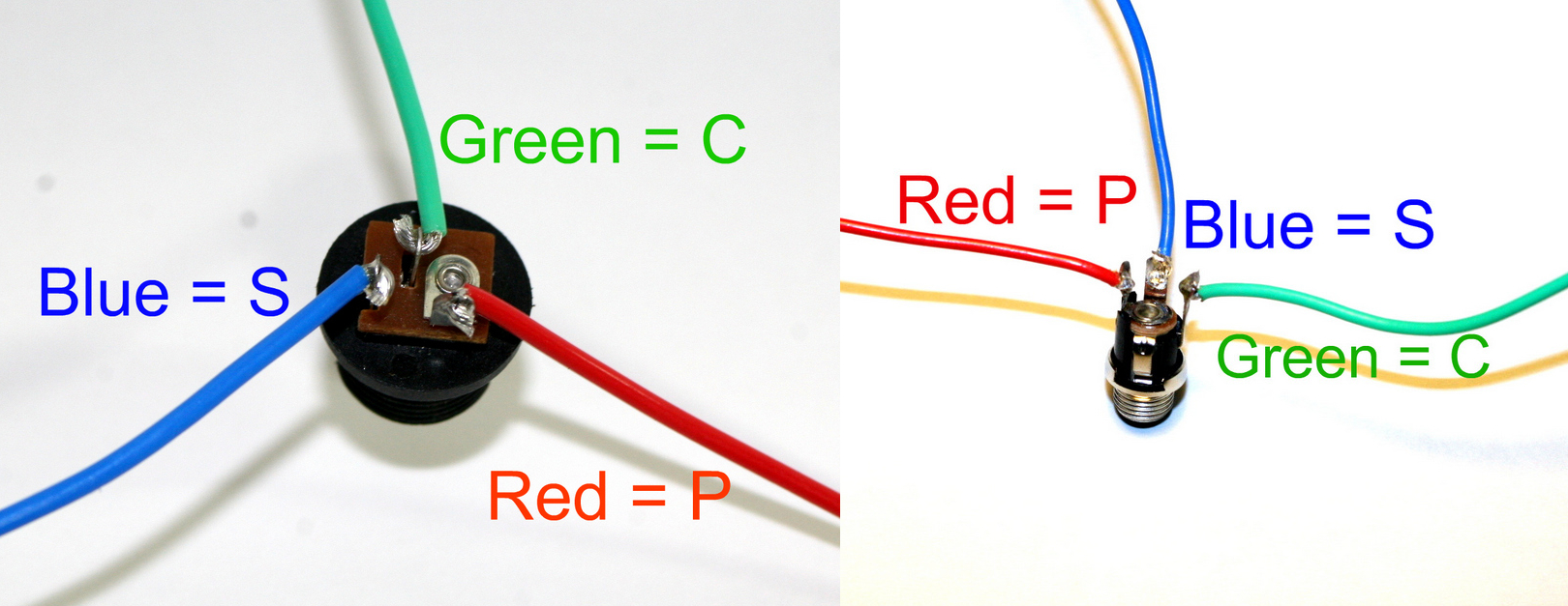
DC Jack Pinout
If you do not want to install the 9V DC jack and only install the 9V battery clip you will have to short the S and C pins for the 9V DC Jack like shown in the picture below*.
* Your PCB may not look exactly like the photo, that is ok. What is important is that you short the same pins as shown in the photo.
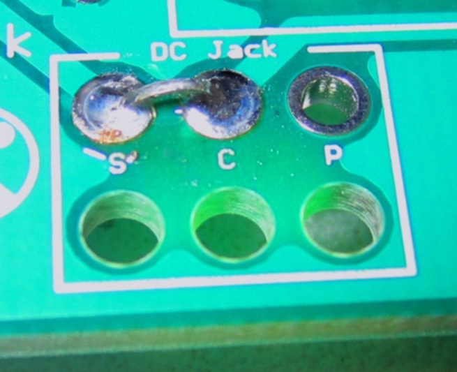
Short these contacts to get the circuit to work without the 9V DC Jack
Potentiometers


Use the pictures above.
The B1k pot will be wired on pins 1 and 2. The B1M pot will be wired on pins 2 and 3.
Don’t worry about the extra pins on the potentiometers.
Wire the pots to the PCB… R4=B1k R5=B1M
When installing the pot, some pots come with nubs near the shaft that may get in the way of installing the circuit into a case. Check for a nub and clip as necessary.

Don’t forget to cut the nubs on the potentiometers as necessary.
On/Off Switch

Wire as shown in the picture above.
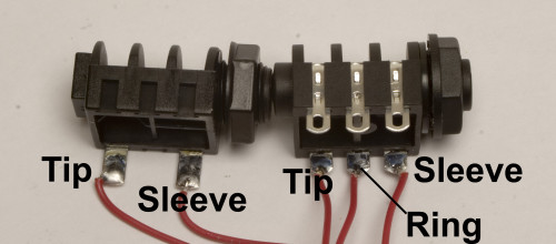
Mono Jack

Wire as shown in the picture above. S=Sleeve (ground) T=Tip
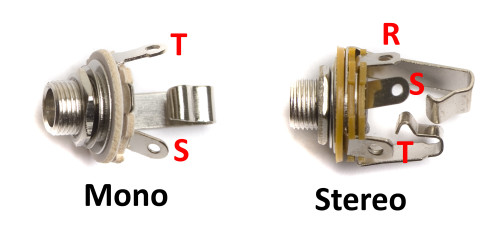
If you are using 1/4″ jacks, please use the diagrams below to wire them in properly.
Optical Resistors

R3 and R1 are the optical resistors. Wire them up in any way you choose!
Complete

Congrats! Note that if you are using an AC adapter, it needs to be 9v center NEGATIVE.
31 Comments