


LM386 Amplifier Assembly Instructions
For a bill of materials with Mouser part numbers, click here.
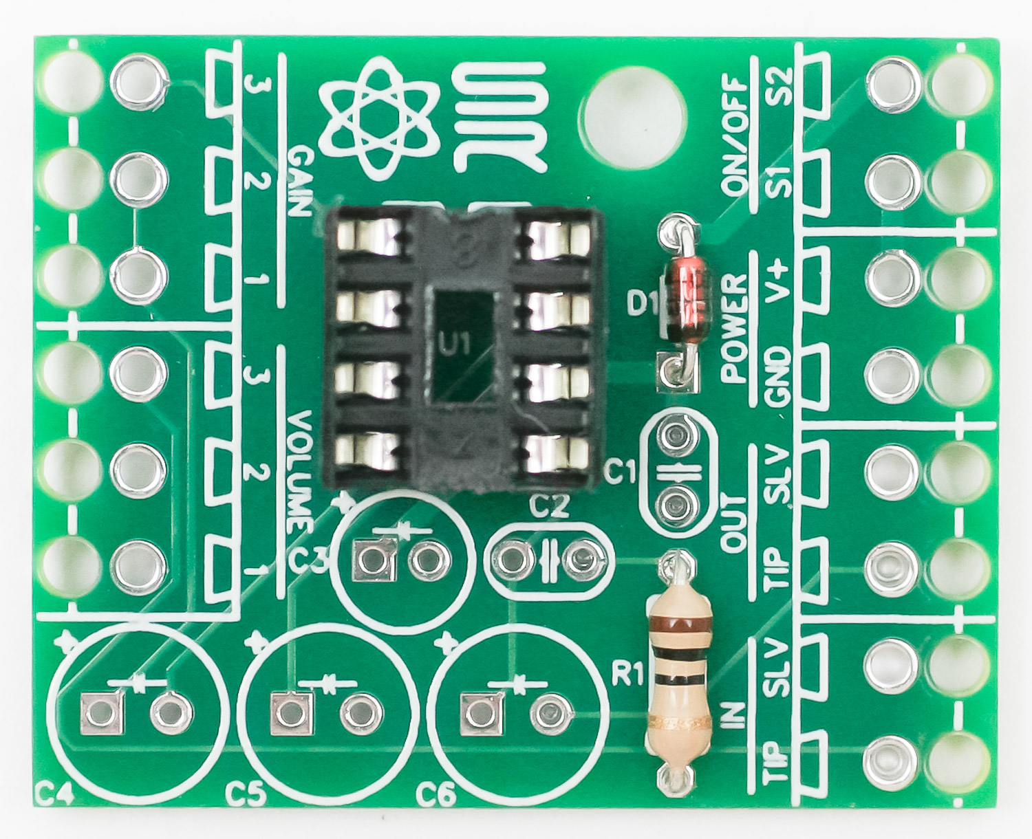
DIODE
 Place the diode into the PCB by aligning the black line on the diode with the white line on the PCB silk screen. Diodes are polarized and must be placed into the PCB in the proper orientation. Carefully turn your project over to solder in place then clip excess leads.
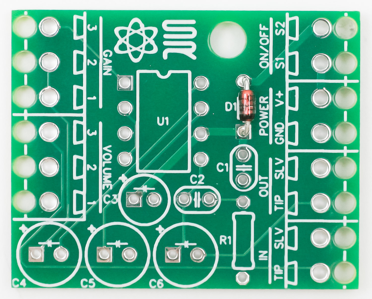
RESISTOR
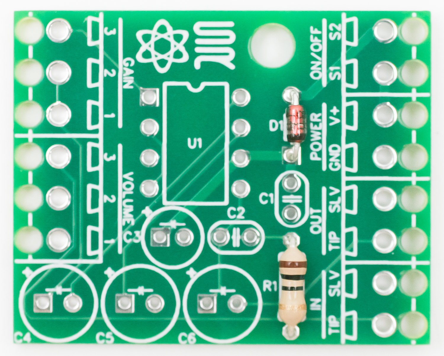
Place the resistor into the PCB as shown above. Resistors are not polarized, so you can place the resistor in either direction. Turn over to solder, then clip excess leads.
IC SOCKET
 Place the IC socket into the PCB by aligning the notch on the socket with the notch on the PCB silkscreen. Carefully turn board over to solder leads in place.
CERAMIC CAPACITORS
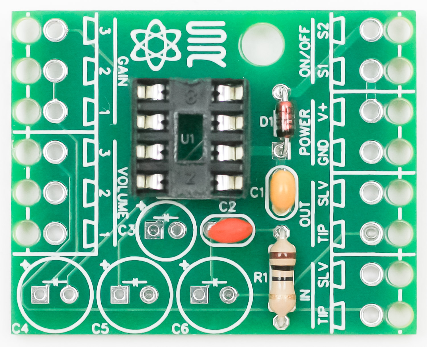 Place the ceramic caps into the PCB as shown above. These caps are not polarized, so you can place them in either direction. Turn over to solder and clip excess leads.
ELECTROYLYTIC CAPACITORS
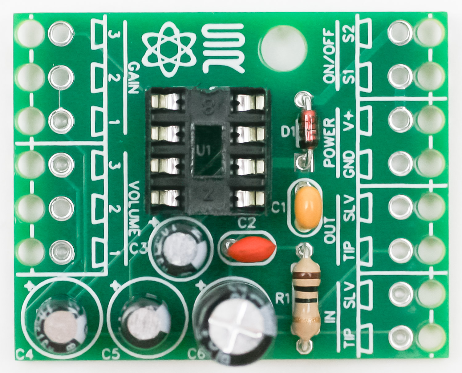 Electrolytic capacitors are polarized and need to be placed in the proper orientation. Place the longer lead of the capacitor into the hole in PCB that has the small “+” next to it. Carefully turn over to solder and clip.
 SCREW CLAMP HEADERS (optional)

The screw clamp headers make it easy to swap out components, but if you like, you can solder your wires directly to the PCB. If you do, loop them through the strain relief holes at the edge of the PCB first.
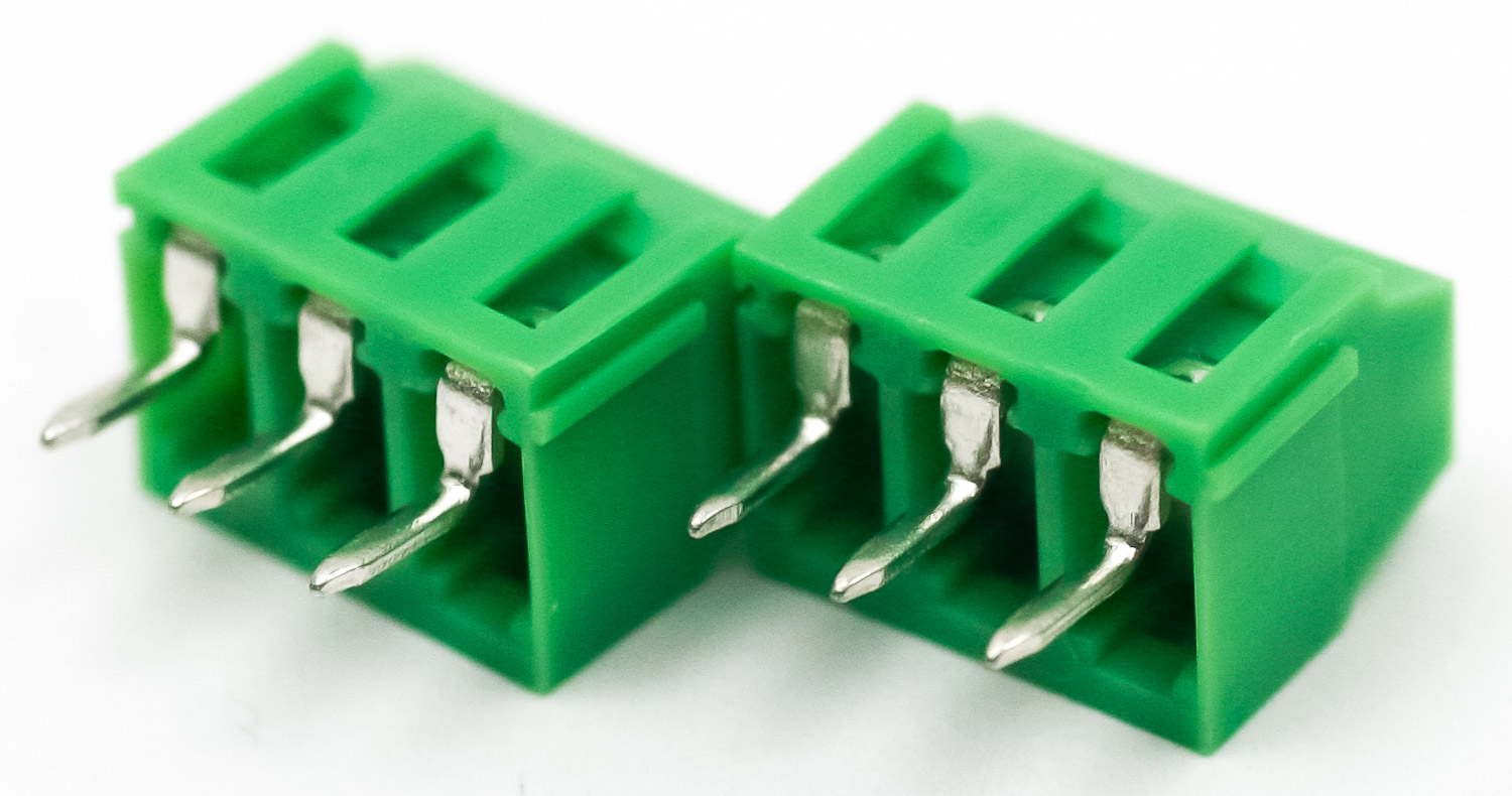
386 Amp Screw Clamp Headers
Connect two pairs of the headers like shown above.
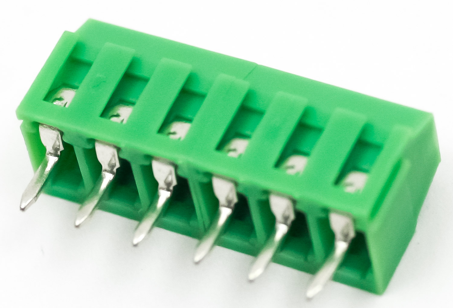
386 Amp Headers Connected
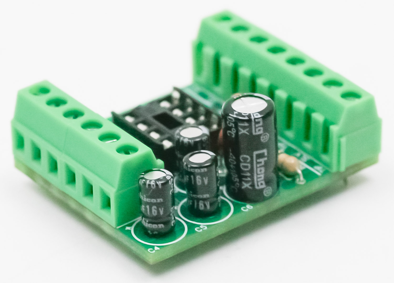
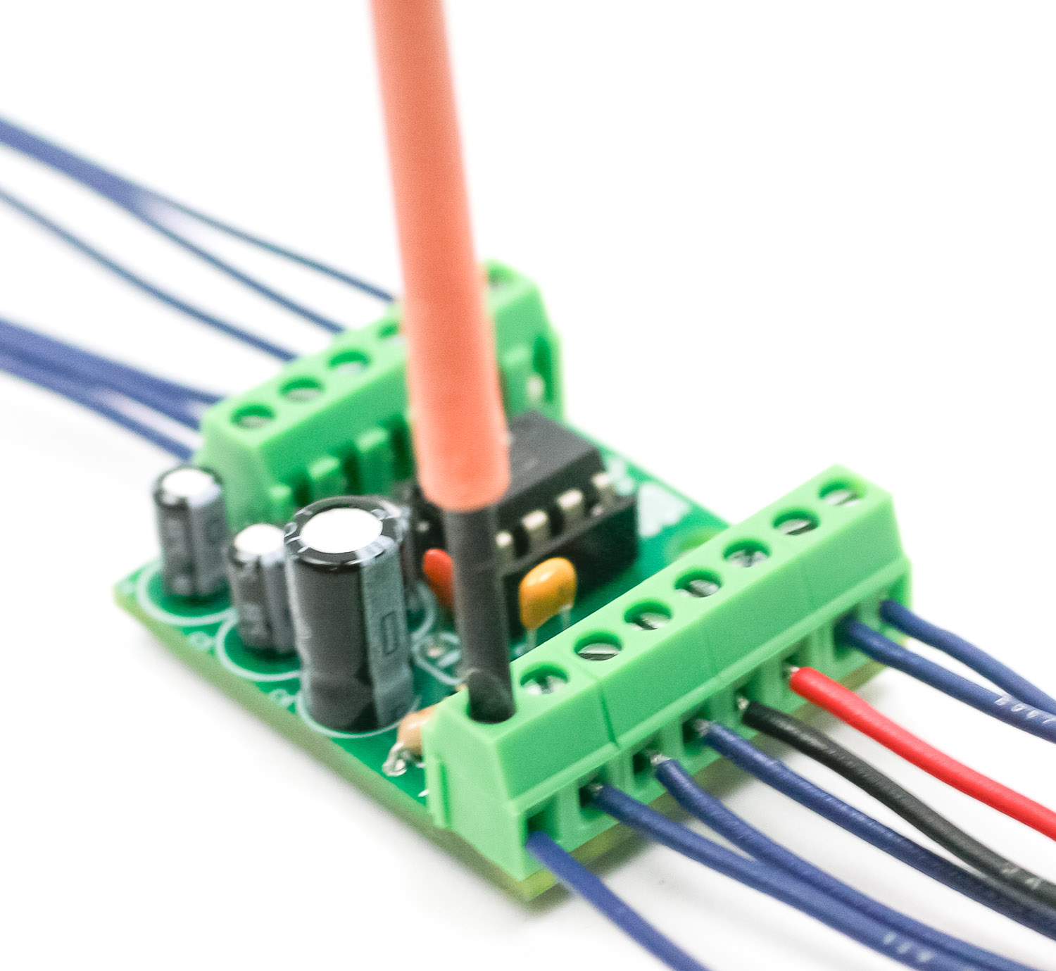
Now solder the screw clamp headers to the PCB but make sure the openings are facing outward!
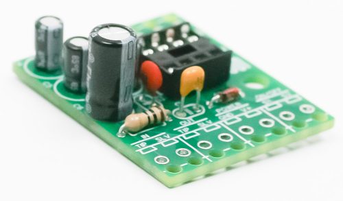
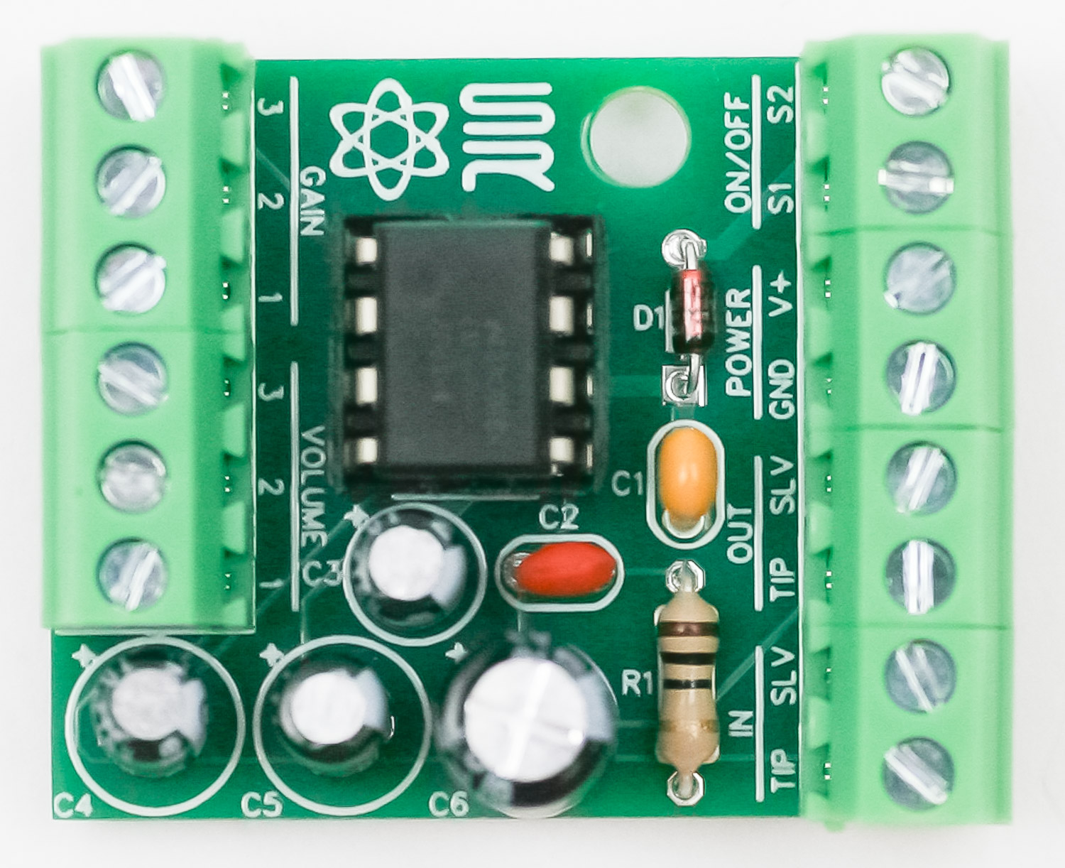
IC
Place the IC into the socket as shown below:
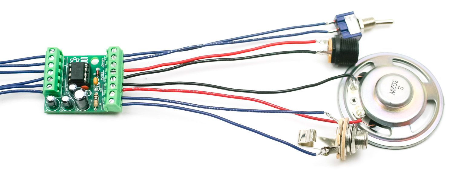
WIRING
The kit includes enough wire to make each wire length about 6 inches (15cm) long, if all the wires are cut to the same length.
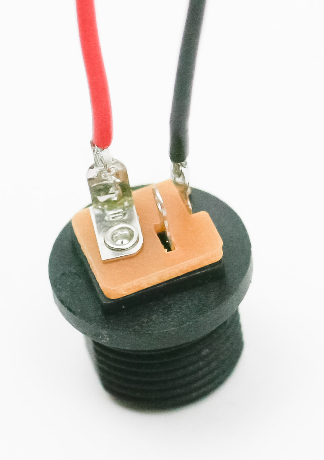
Solder wires to the DC jack. This setup is for center positive polarity. You can reverse the wires to make the wiring center negative. If you do, make sure you don’t use a metal DC jack on a metal case or you will have a grounding issue.
Wire the rest of the components as shown below: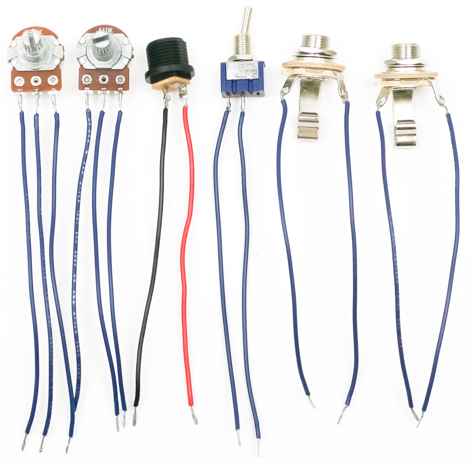
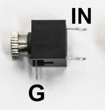
If you are using the 3.5mm jacks, wire the TIP (IN) and the SLV (G) as in the picture below:
Connect the wires to the screw clamps as shown below. If using the 9V battery snap connector, connect the red lead to V+ and the black lead to GND.
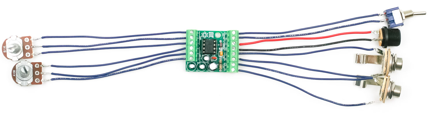
Shown below is the optional speaker wiring configuration:
You’re ready to plug in and play! A wood screw and spacer is included if you want to screw the circuit into a case.