


Important Links
Product Page
Store Page
Assembly Instructions
Bill of Materials
Schematics
Drill Template
Capacitor and Resistor Lookup Guide
The DS-8 Clone Drum Synth is one of our favorite new circuits. There is a lot of sonic potential and functionality built into the circuit. If the Drum Synth is your first build, don’t worry about this project being difficult; despite the number of components, the build process is fairly straightforward.
Let’s get started.
Component Layout

Check your kit to make sure you have everything you need to finish the circuit. If you’re unfamiliar with electronic components, don’t worry; the pictures are great guides to help you identify the similar components.
If you’re missing anything from your kit, please send us an email and we’ll get it out to you ASAP.
Alright, on to the build.
Assembly
Attention: Changes may occur after the Assembly Instructions are created and the photos may not reflect those changes. Always use the BOM to verify the placement of components.
PCB Components
The first components in our build are soldered directly to the PCB. This helps keep the working area compact and wire-free. If you make a mistake and have to resolder a component, you will be able to do so without a wire getting in the way of your solder iron.

Place the 4 IC sockets on the PCB and solder as shown in the picture. Note the cut-outs and dots on the body of the ICs; these identify where pin 1 is located and how the socket should be placed. If you are in doubt, double-check the picture.

The DS-8 Clone circuit has a lot of resistors. I suggest inserting half into the PCB and then soldering them, clipping the leads, and repeating for the other half. If the resistors are becoming tangled with each other, simply solder what you have and then move on to more.

Insert the capacitors according to their reference ID. For the electrolytic capacitors, pay attention to the polarity markings on both the capacitor body and the PCB. Electrolytic capacitors have a colored band and a shorter lead to denote the negative pole. The square through-hole on the PCB has a silkscreen ‘+’ to denote positve polarity.

The next components to solder to your PCB are the diodes, D1, D2, D3. Diodes are polar components and require you to pay attention to lead placement. On the diodes there is a black band near one of the leads – this designates the negative lead. The PCB silkscreen makes the placement obvious. The LED has a flat edge on the base of its body as well as a shorter lead, which identifies the negative lead. Also picture above is the voltage regulator,

Q1, Q2, and Q3 are easy to insert correctly because of the silkscreen on the top layer of the PCB. You may need to spread the leads outward slightly in order to get the transistor to fit. You should leave a little room between the bottom of the transistor and the PCB.

For the potentiometers, you have a couple of options based on how you plan to mount your circuit. The board layout allows you to directly mount the potentiometers to the PCB or you can attach wires to them to extend their reach. Remember that longer wires can always be cut and you’ll save yourself some frustration and extra work.
* Note: Standard values for the potentiometers are printed on the PCB. These are only suggestions and you can use lower or higher value pots for most. You can also wire resistors in their place or add an additional circuit to develop your circuit. Currently, we are experimenting with tap tempo circuits and external LFOs. If we come up with anything noteworthy, you will find it in the Mods section below. If you come up with anything, send us a schematic and we’ll give you credit as well as plug your projects or website. *
When installing the pot, some pots come with nubs near the shaft that may get in the way of installing the circuit into a case. Check for a nub and clip as necessary.

Don’t forget to cut the nubs on the potentiometers as neccesary.
Wired components
For this portion of the build instructions, the remaining components will be attached to the PCB via wires. Keep in mind how you are going to mount your circuit’s components. You can also mount your components in your case and wire them to the PCB. Either way is fine, but troubleshooting a non-functional circuit that is already mounted may require you to poke around tight spaces with a soldering iron (not fun!!!).
Reverse Polarity Protection & Piezo Trigger
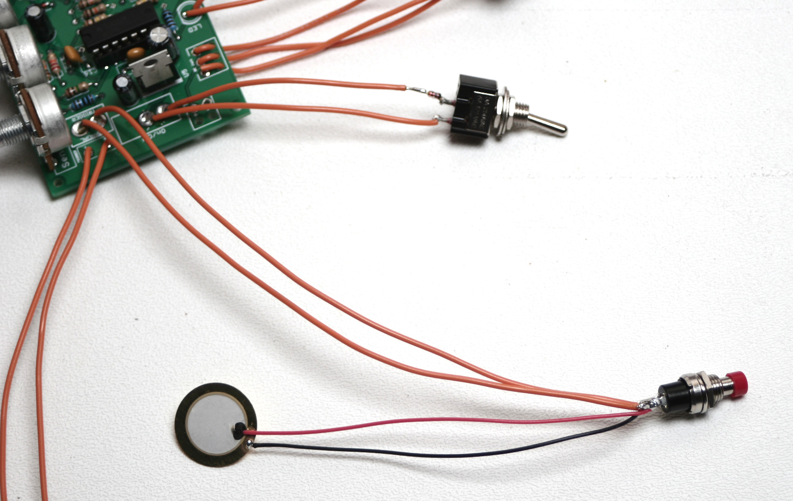
Kits purchased after 5/7/14 come bundled with a piezo trigger and additional 4148 diode – both are optional and omitting either will not affect the functionality of the circuit. The piezo is nonpolar and may be connected in any orientation provided that one lead is connected to each leg of the momentary trigger switch. You may also wire one lead to each trigger pad on the PCB if you choose not to install a momentary trigger switch. Follow the photo below for polarity protection diode orientation:


The next two wired components are the two switches. The SPST switch (SW2) has two terminals and it does not matter how they are attached to the PCB. The SPDT switch (SW1) needs only the center solder terminal to be inserted into the middle PCB through-hole (shown as the red wire in the picture below). You can insert the remaining wires into either through-hole and it will work. The switch’s toggle determines which capacitor (C10 or C11) will be used to color the noise portion of the circuit.


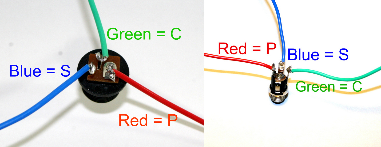
Included in your kit are three 1/4″ mono switched jacks. If you have never used these types of jacks, the number of solder terminals may be confusing. You will only be using two, but there are upcoming mods you can perform that will expand the circuit’s potential beyond just the standard Drum Synth sound. So, with the jack’s opening facing towards you, solder two wires to the terminals on the left. The one closest to you (shown as blue wire in the picture) will attach to the ‘-‘ PCB position. Solder the remaining wire (red) to the ‘+’ position.

DC Jack Pinout
Last but most important are the power connectors. The 9V battery jack connects to the board with the red wire to the ‘+’ and the black wire to the ‘-‘. You may have noticed that I used colored wires throughout these instructions; this was intentional. Troubleshooting a malfunctioning circuit is 100% easier when you can quickly identify misplaced wires by visual inspection. Use one color and you will see exactly what I mean when you make a tiny mistake.
*Note: if you are not using a DC Power Supply to power your DS-8, use a jumper wire to connect the DC Jack’s C and S pads together.*
If you do not want to install the 9V DC jack and only install the 9V battery clip you will have to short the S and C pins for the 9V DC Jack like shown in the picture below*.
* Your PCB may not look exactly like the photo, that is ok. What is important is that you short the same pins as shown in the photo.
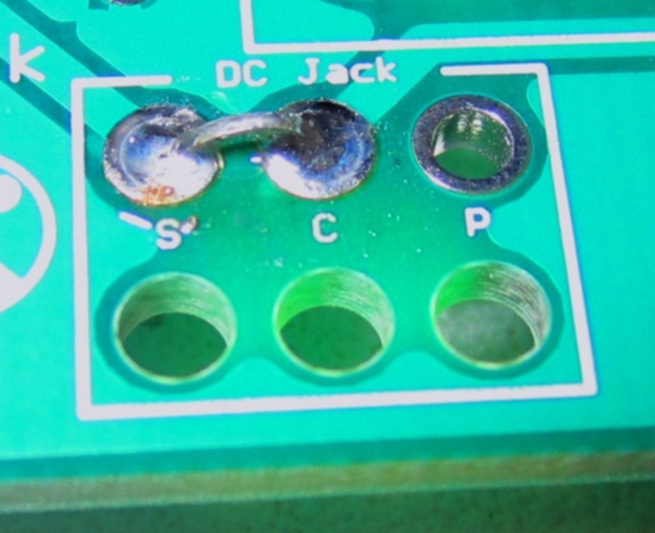
Short these contacts to get the circuit to work without the 9V DC Jack
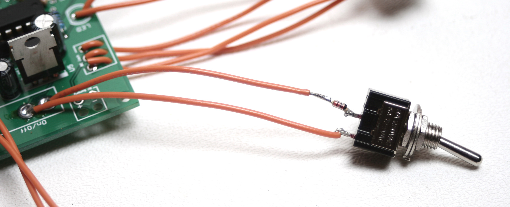
Following the image below, you want to take one of the wire from the on/off switch and connect it to the S pin for the DC adapter jack and install an N4148 diode between the switch and the S pin for the DC jack with the black line on the diode being towards the switch.
DS-8 Completed

Alright! We are done building the DS-8 Clone Drum Synth! Now, let’s test our circut. Turn all of the potentiometers to a somewhere-in-the-middle position. Insert a trigger source (Piezo Drum, 555 Timer Circuit, synth output, etc.)into the Trigger jack. Connect the circuit at the Out jack to an amplifier with a 1/4″ cable. Do you hear anything? If not, adjust the Level and Sensitivity pots until you get a sound. Should you still hear nothing, switch trigger inputs. If you still don’t hear anything, go back through the instructions and double-check all of your component placement and wiring.
When you finally get a sound out of all your hard work, take a break and bask in your success. Not everyone has the patience and skill to be able to create their own synths, so congratulations on a functional build!
After you’re done playing around with your finished circuit (several hours later), take a quick look at the Mods section to add functionality or circuit bend your own circuit. There’s a lot you can do to make your own unique sounds.
Thanks for purchasing a kit from us and we hope that you are happy with your circuit. If any of these instructions are unclear or you have a question, send us an email. We like it when our customers build our circuits. Include detailed pictures if you are stumped on where the problem lies with your circuit. Any feedback we get helps to improve these instructions as well as help you past any stumbling blocks.
29 Comments