


Important Links
Product Page
Store Page
Assembly Instructions
Bill of Materials
Schematics
Capacitor and Resistor Lookup Guide
Welcome to the NEW Atari Punk Console w. CV Input Assembly Instructions! If you’re new to circuit-building, this is a great kit because it’s easy and makes some crazy sounds. Let’s get started!
BOM Layout

If you received your kit and you’re ready to build, the first step is to check to see if you have all of the parts. Check your kit against the APC BOM. If you’re missing anything, we’ll send it to you free of charge.
Assembly
Attention: Changes may occur after the Assembly Instructions are created and the photos may not reflect those changes. Always use the BOM to verify the placement of components.
PCB Components

Line up the half-moon notch on the IC socket with the notch drawn on the PC board.
Capacitors

The next part of our build are the capacitors. C1, C2, and C4 are non-polar ceramic capacitors, so their leads can go in either through-hole their silkscreen designates. They look similar, but they have different values that are printed on their body in small lettering. C1 will have a ‘103’ and C2/C4 will be labeled ‘104’.
C3 and C5 are 10μF polarized electrolytic capacitors. These capacitors must be placed correctly for the circuit to function correctly. Most electrolytic capacitors have a thin band on their body (grey in the picture above) that denotes the negative lead. New electrolytic capacitors will also have a longer positive lead.
On the PCB, C3’s silkscreen identifier has a square through-hole with a ‘+’ next to it. This is where the positive lead is inserted. The negative lead is inserted into the circle through-hole.
Resistors/Diode

There are 4 resistors to place onto the PCB. R1 and R2 are 1kΩ resistors (colored brown-black-red-gold), R3 is a 4.7kΩ resistor (colored yellow-violet-red-gold), and R4 is a 10kΩ resistor (colored brown-black-orange-gold).
The Schottky diode will be used for D2. Match up the black (negative) band on the diode with the white band on the PCB.
Wired Components
Potentiometers

Our first wired components to add to the PCB are Pot1, POT2 and POT3. Pot1=A1ook Pot2, Pot3=B500k

Match the PCB through-holes to the potentiometer solder lug numbering above. Solder wires to the potentiometers, then insert them into their corresponding position.
When installing the pot, some pots come with nubs near the shaft that may get in the way of installing the circuit into a case. Check for a nub and clip as necessary.

Don’t forget to cut the nubs on the potentiometers as neccesary.
Power Connections/Jacks

Connecting the 9V battery adapter jack is easy, so we’ll do this first. The red wire is connected to the square through-hole next to the ‘+’ silkscreen. The black wire is connected to the circle through-hole next to the ‘-‘.
DC Jack Pinout
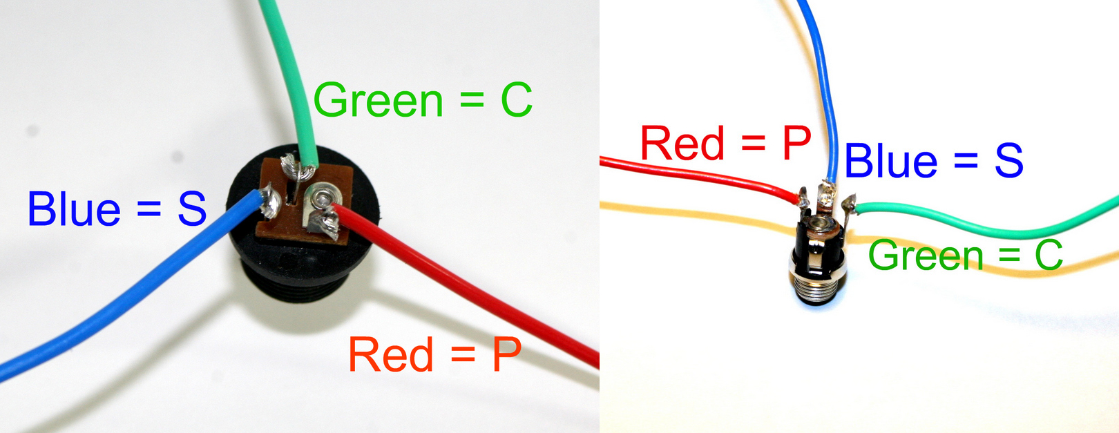
The DC Jack is fairly straightforward: P = Pin, S = Sleeve, C = Switch. Connect three wires to the DC Jack’s solder terminals and, using the picture above as a reference, connect them to the PCB at their respective through-holes. The center pin will be negative.
If you do not want to install the 9V DC jack and only install the 9V battery clip you will have to short the S and C pins for the 9V DC Jack like shown in the picture below*.
* Your PCB may not look exactly like the photo, that is ok. What is important is that you short the same pins as shown in the photo.
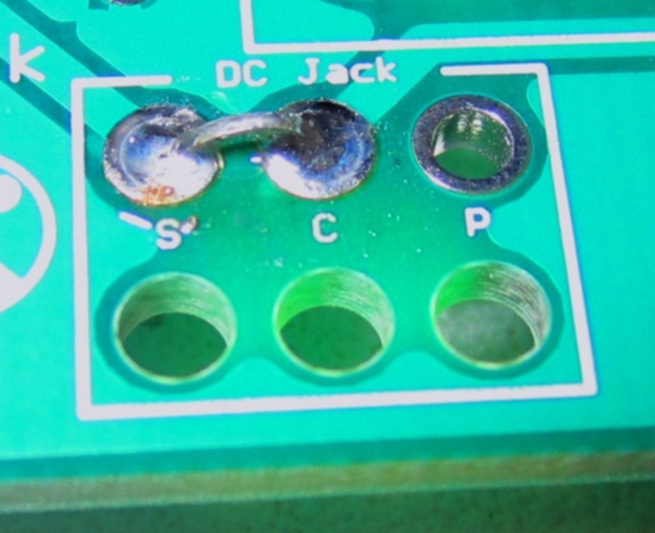
Short these contacts to get the circuit to work without the 9V DC Jack
Mono Jacks

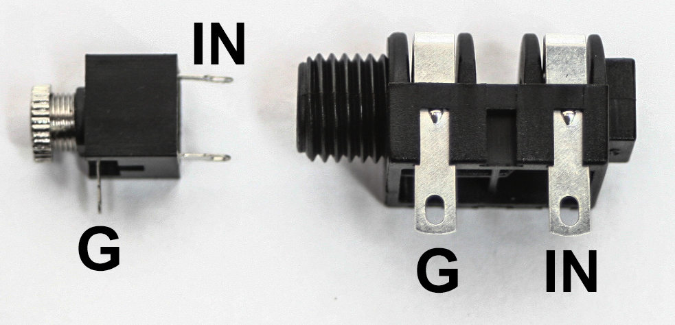
Tip (IN) and sleeve (Ground) on a 3.5mm and 1/4 inch jack
The APC needs three mono jacks for the ‘CV-IN’ and ‘OUT’. There are two solder lugs on 1/4″ mono jacks, with the ‘S’ standing for Sleeve/Ground and ‘T’ standing for Tip. On the PCB, locate the through-holes for ‘CV-IN’ and ‘OUT’ Both of these have a ‘T’ (IN) and an ‘S’ (G) next to the through-holes. Using the picture above, connect the mono jacks to the PCB.
SPST On/Off Switch

Wire the power switch as shown in the picture.
Wired LED

LEDs are polar components just like electrolytic capacitors. They also have a longer positive lead. D1 indicates whether or not the circuit is receiving power and will be the first indication that your circuit is built correctly, so this step is important.
To solder this straight to the board, insert the longer positive lead into the circle through-hole and the shorter negative lead into the square through-hole.
To wire the LED for a case, make hooks at the end of the LED leads; solder the wires to the leads. Make sure the wire connecting to the longer lead goes into the circle through-hole (which is positive) and the shorter lead into the square (negative) through-hole.
Lastly, add in the IC, aligning the notch on the chip with the notch on the socket.
Congratulations, that’s the end of the assembly! Put a battery into the 9v battery adapter jack, connect an external amplifier, turn the circuit on, and turn up Pot1. Your LED should light up, and you should have a gnarly sound coming out of your amp. If it doesn’t work, go back through the instructions and carefully check all of your work.
Have fun with your new hand-made APC!!
45 Comments