


Important Links
Product Page
Store Page
Quick Start Guide
Assembly Instructions
Bill of Materials
Schematic
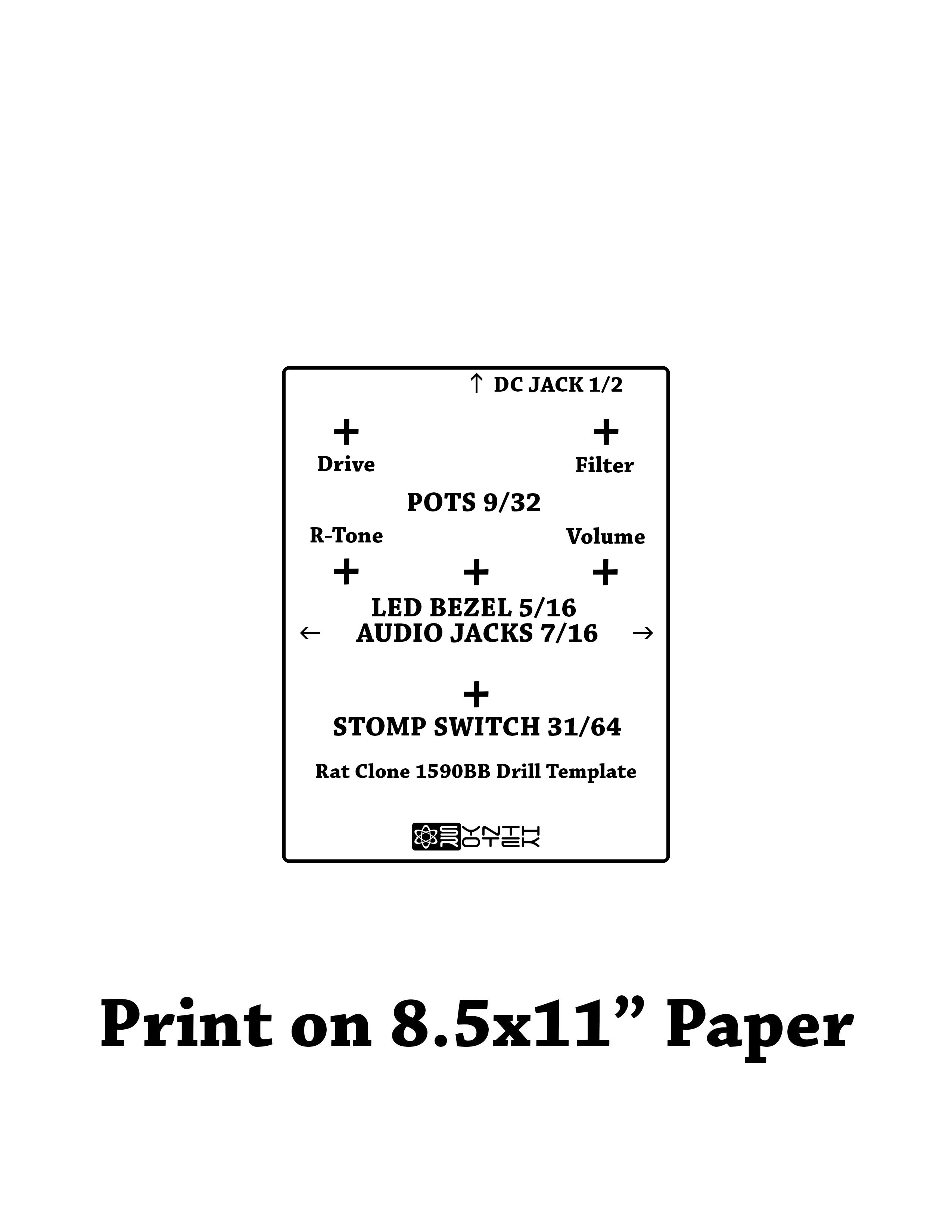
Drill Template Capacitor and Resistor Lookup Guide
RATATAK LM 308 Distortion Pedal Kit WIRED Assembly Instructions
Wired Rat Visual BOM
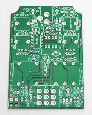
LM 308 Rat Clone PCB
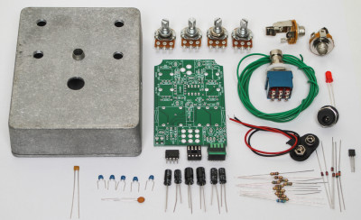
Thank you for purchasing our new Wired Rat Clone Kit. If you are looking to build this kit into a compact 1590B sized metal project box, please consult our PCB Mount version of this kit. Please follow these instructions in order, as it can be tricky to build and insert into the enclosure. ALWAYS REFER TO THE BOM FOR THE MOST RECENT AND BEST COMPONENTS. DO NOT RELY ON THE PHOTOS ALONE!
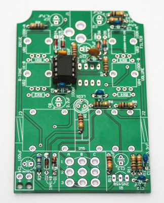
RESISTORS & DIODES
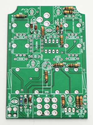
Rat Clone Resistors and Diodes
Please consult the BOM prior to adding any component. While we try to keep the same looking components in stock, variations of appearance will happen. Do not rely on the photos alone. If you need help reading components, check out our resistor and capacitor code charts in the menu at the top of the page. Add all of the Resistors and diodes, solder and carefully trim your leads. D5 and D6 are the germanium diodes. PLEASE NOTE, RX2 is not populated in the above photo, but there needs to be a 100 ohm resistor in this place.
IC Socket, IC and Ceramic Capacitors
Rat Clone IC and Socket
Now add the IC socket by matching the notch in the socket with the notch on the PCB silk screen and then place the IC in the socket carefully and again align it with the notch.
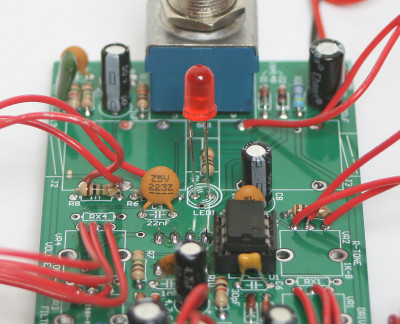
Electrolytic Capacitors and Transistor
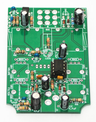
Wired Rat Clone Capacitors and Transistor
Electrolytic Capacitors and Transistors are polarized and thus can only be placed into the PCB one way. Insert the longer lead of the capacitors into the hole that has a “+” next to it. Align the transistor with the silk screen on the PCB by matching the flat edges. Solder and clip leads.
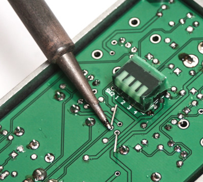
Clipping Diodes Selection Piano Switch
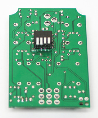
Wired Rat Clipping Diode Piano Switch
Place the piano switch as shown above. The switch will allow for symmetrical and asymmetrical clipping diode selection. Pressing down 1 and 2 of the piano switches set up the pedal for symmetrical silicone diode clipping and 3 and 4 set up the pedal for symmetrical germanium diode clipping. Mess around with these to your liking to achieve your desired tone after you pedal is complete.
Wiring Potentiometers and Jacks
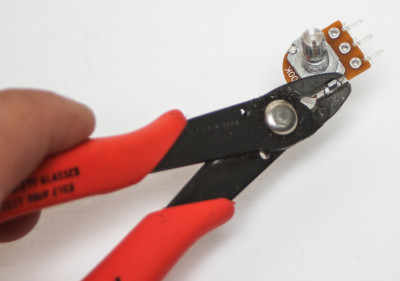
Trim Potentiometer Notch
First trim the metal alignment notch on the pots as shown above. Failure to do so will result in a canted mount.
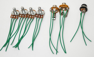
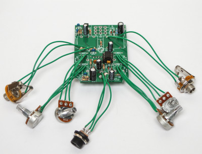
Jacks, Pots and DC Jack Wiring
Next, trim the desired amount of wire, trim both ends and then wire as shown above. If you have purchased our pre-drilled enclosure, the lengths above are more than sufficient.
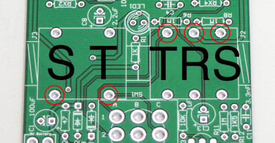
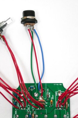
WIRED RAT AUDIO JACK WIRING
Connect the wires for the audio jacks into the red holes corresponding to the picture above and below.
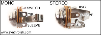
1/4″ Metal Audio Jack Wiring
Next, wire the DC jack as shown below. The colored wire is for reference only.
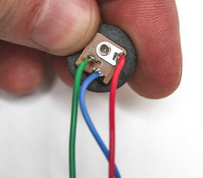
wiring the dc jack
wiring dc jack to pcb
Wire the potentiometers as shown below in order for the pots to turn the correct way.
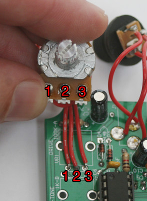
Potentiometer Wiring Order
Wired Rat with Wires
3PDT Stomp Switch
Now add the stomp switch as shown below and solder in. If the fit is tight, just press it through with some effort.
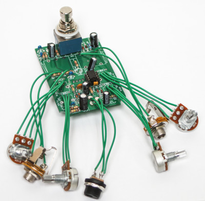
Wired Rat 3PDT Stomp Switch
LED PLACEMENT
There are 2 ways that you can solder in your LED. You can either populate the LED loosely by placing the project into the enclosure and through the LED bezel and then pushing the the LED tight then soldering down (photos 1 and 2). Or you can wire it it up with the provided wire and use the plastic LED crimp (photo 3). At any rate, make sure you align the flat side of the 5mm LED with the flat side on the PCB silk screen graphic.
Wired Rat LED #1
Soldering LED #2
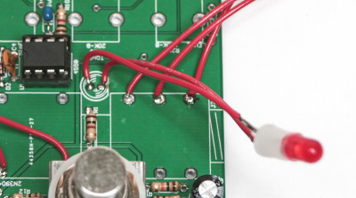
Wired LED #3
Finally solder in the 9V battery snap and place the pots, and jacks in first and gently tighten. Then align the LED and stomp switch into their respective case holes and press through and tighten down nuts. Now is a good time to test your circuit BEFORE placing it into the enclosure.
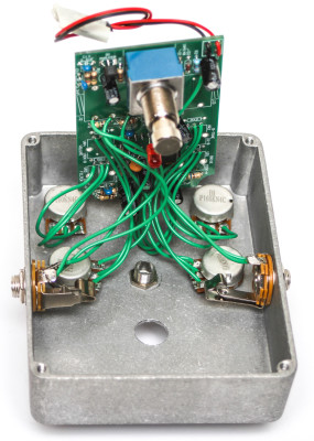
Placing the project into enclosure
Once your project has been all tightened down, you can place the enclose back plate on and screw down. Feel free to get crazy with some paint or DIY graphics and rock out! Having troubles with your circuit? CLICK HERE
21 Comments