


Important Links
Product Page
Store Page
Assembly Instructions
Bill of Materials
Fuzz Face Drill Template
Schematic
Capacitor and Resistor Lookup Guide
Welcome to the Genuine Arbiter Fuzz Face Clone Kit Instructions! It’s a great circuit and it’s an easy build, so let’s get started! This kit can be purcahsed with either Germanium AC128 PNP transistors or BC588 Silicon PNP transistors.
BOM Layout

DA Fuzz Face Layout
Assembly Instructions
Attention: Changes may occur after the Assembly Instructions are created and the photos may not reflect those changes. Always use the BOM to verify the placement of components.
PCB Components
Resistors

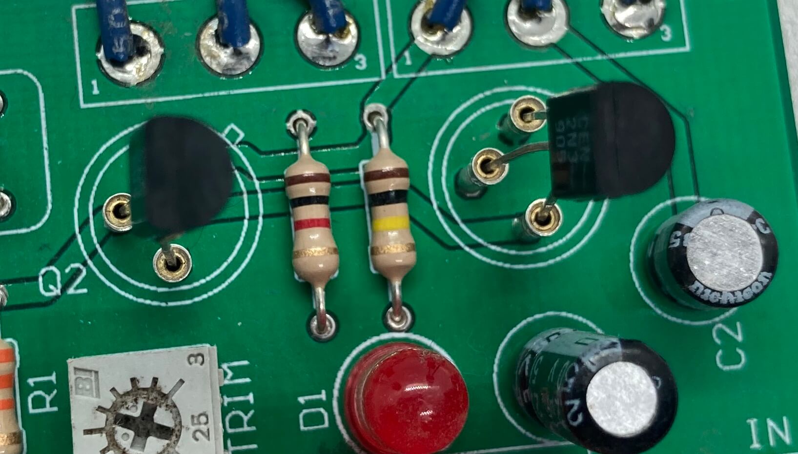
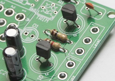
Locate the silkscreen component identifiers for R0, R1, R2, R3, R4, and R5. Insert each resistor into the correct through-holes and solder them to the board.
Capacitors

When placing C1 and C2, use the picture above to help you position these electrolytic capacitors. Note the black band; this indicates the negative polarity lead of the capacitor. To further assist you, the PCB has a ‘+’ and a square through-hole for the positive lead and a circle through-hole for the negative lead.
C3 is a ceramic capacitor and it does not matter which lead goes into which hole.
Transistors
Make sure your transistors are oriented correctly! Each type faces a different direction!
2N3905 Transistor Orientation

Germanium AC128 PNP Transistor Orientation
FOR OLDER KITS ONLY!!
BC558 PNP Transistor Orientation
Pay special attention when placing the transistors onto the PCB. Each of the three leads has a specific function and the circuit will not work if they are placed incorrectly.
When using the silicon 2N3905 or BC558 transistors, follow the orientation in their respective photos.
Germanium transistors: Line up the little tab on the transistor with the tab on the board as shown in the first picture above. Q1 gets the lower gain transistor (if you are using Synthrotek’s transistors, it will be marked with a black dot). Q2 gets the higher gain transistor.
The trimpot has three leads. Orient the trimpot as shown in the picture above and insert the leads onto the PCB. If the leads are bent, gently bend them to conform to the through-hole layout on the PCB. Once the circuit is completely built, you can adjust this trimpot to color your sound to your needs.
That is all for on board components.
Wired Components
Potentiometers
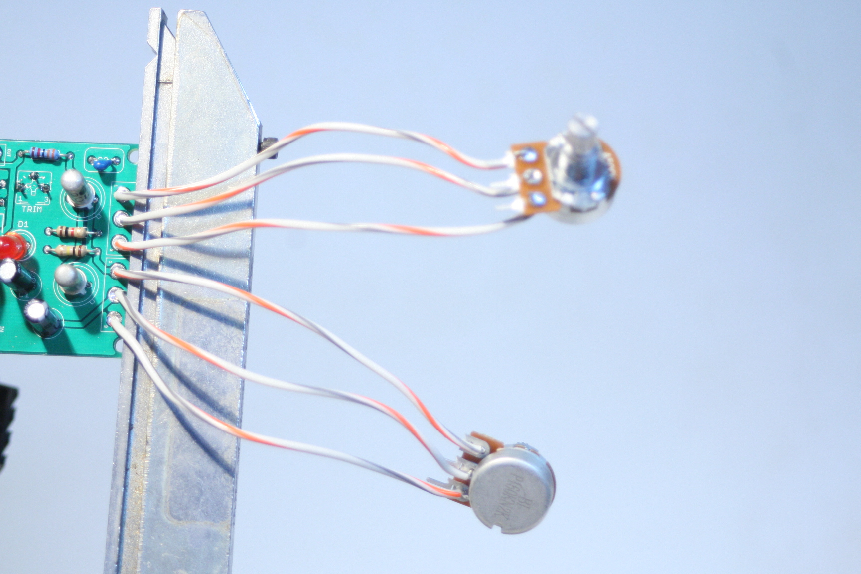
Wire the pots exactly as shown in the picture above (the top one is the A500k and the bottom is B1k). Make note that the B1k pot is reversed from the orientation that most of our pots use.
We suggest soldering wires to the potentiometers before attaching them to the PCB. Having to de-solder a too-short wire from the PCB is an extra step that can be avoided. As always, use more wire than you think you will need; wire can always be cut.
When installing the pot, some pots come with nubs near the shaft that may get in the way of installing the circuit into a case. Check for a nub and clip as necessary.

Don’t forget to cut the nubs on the potentiometers as neccesary.
Input/Output Jacks and Power Jacks
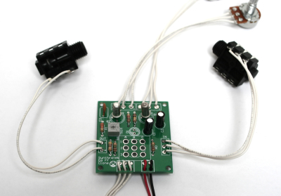
The ‘In’ Jack of the Arbiter Fuzz Face Clone circuit uses a 1/4″ stereo jack which turns off the power sources when nothing is plugged into it. When you plug a mono plug into the jack, the circuit receives power.
Stereo jacks have three solder lugs for the 3 different parts of the stereo signal: Tip, Ring, and Sleeve. On the PCB, they are identified as ‘T’, ‘R’, and ‘S’. Attach each solder lug on the jack to their respective PCB connection. Make sure to use the solder lugs as pictured above.
On the other side of the board is the ‘Out’ PCB connections. They are marked ‘T’ and ‘S’ for ‘Tip’ and ‘Sleeve’. Mono jacks only have these two connections, so they are easy to wire up.

The 9V battery jack is easy to put onto the PCB. Take the red wire and insert it into the square through-hole with the silkscreened ‘+’. The black wire goes to the circle through-hole marked with a ‘-‘.
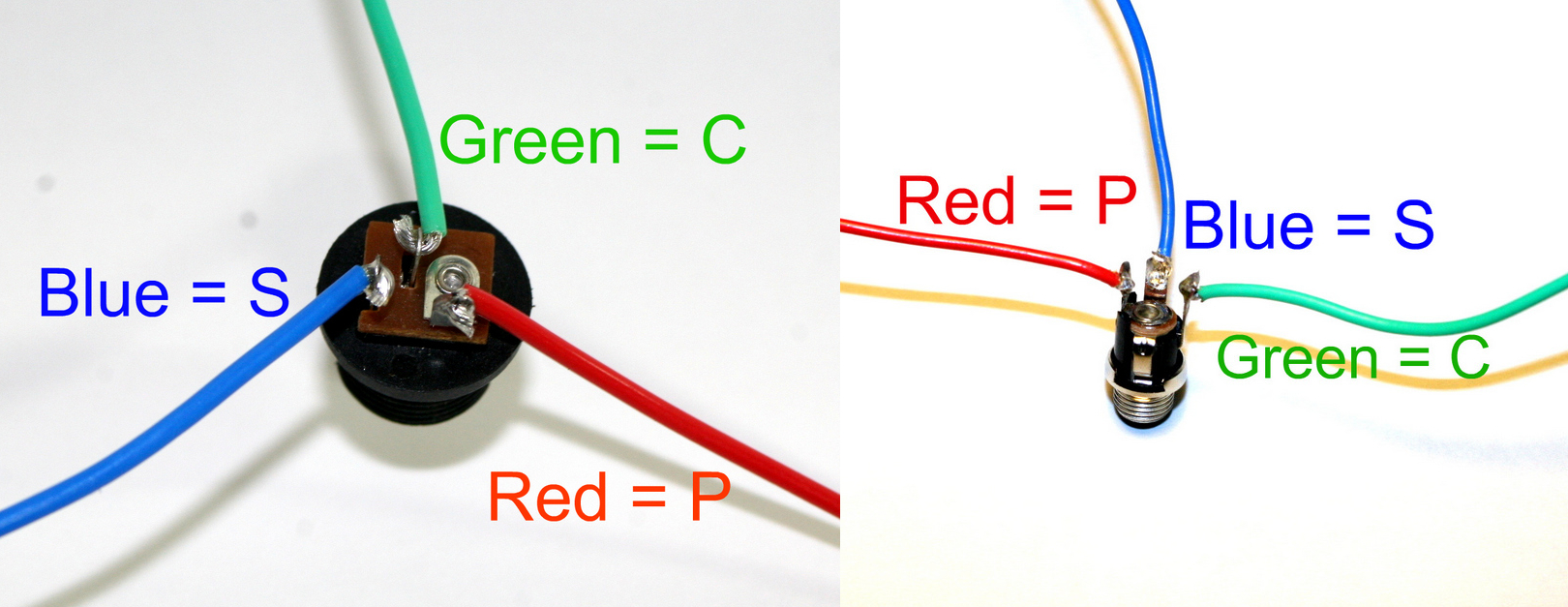
DC Jack Pinout
The DC Jack has three solder terminals that connect to the PCB. Use the picture above and the silkscreen on the PCB to place the wires correctly. The DC Jack allows you to power your circuit with a wall wart and disconnects the 9V battery from the circuit, saving money on expensive batteries.
NOTE: please remember to use a 9 volt center positive power supply. Using the incorrect power supply polarity will damage your circuit.
If you do not want to install the 9V DC jack and only install the 9V battery clip you will have to short the S and C pins for the 9V DC Jack like shown in the picture below*.
* Your PCB may not look exactly like the photo, that is ok. What is important is that you short the same pins as shown in the photo.
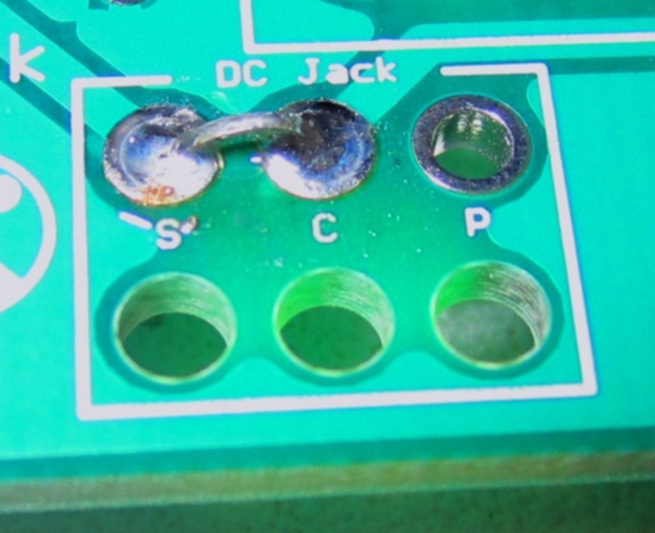
Short these contacts to get the circuit to work without the 9V DC Jack
LED
Insert the LED through the plastic insertion mount (if needed) and solder wired leads to both legs. Connect the wire leading from the flat side of the of LED to the solder pad on the board that is closest to the flat spot on the silkscreen. The picture below shows the flat spot (although the led is board-mounted). You may omit wiring the LED and mount it directly to the PCB. The photos below illustrating stomp switch wiring show the LED installed in this configuration.
Stomp Switch

Stomp Switch Help
Line up the number code from the switch to the board exactly how it is labeled in the picture (above and below.)
Make sure the flat blue side of the stomp switch is facing up when comparing it to the picture below. Either Blue Side will work fine. AND YOU CAN MOUNT THE STOMP SWITCH DIRECTLY TO THE PCB IF DESIRED.

Stomp Switch Help

Stomp Switch Wiring
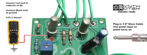
Biasing Instructions:
Power on the pedal and insert a cable into the input jack. For the circuit to be optimally biased, the collector of Q2 needs to be at 4.5 volts. (When connecting the Arbiter Fuzz Face Clone circuit to your multimeter as shown in the photos below, your meter will read -4.5V.) The 20K trim pot is used to dial in this value. All you need to do is connect your leads to a ground on the PCB and the collector of Q2 to get this reading.
 Arbiter Fuzz Face Clone Biasing Guide
Congratulations, that’s the end of the instructions for the Arbiter Fuzz Face Clone circuit! If everything is wired/connected properly, you should have a fully functional fuzz pedal. Remember to adjust the trimpot to get the sound you want from your new pedal and have fun!
107 Comments