This product has been discontinued.
Important Links
Product Page
Assembly Instructions
Assembly Notes
Bill of Materials
Schematic Page
16 Step MOD
Drill Template
Capacitor and Resistor Lookup Guide
Adding the 16 Step MOD to the 16 Step Sequencer
Step 1
- Remove C27 and C28
- Remove R89 and R90
Step 2
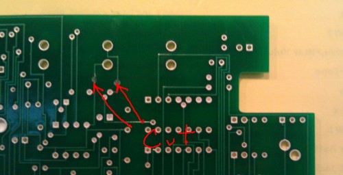
- Isolate old switches by making 6 cuts to the traces on the board
- Cutting can be accomplished by using a box cutter, razor blade or a dremel (cutting blade works, but I prefer using an engraving bit)
- Cut locations
- Top of board
- Left of the top hole for SW 21
- Right of the bottom hole of SW21
- Below the bottom hole of SW21
- Right of the bottom hole of SW19
- Bottom of board
- Both traces leading to SW 20
- Top of board
Step 3
- Solder on (2) 100kΩ resistors and (3) 0.1uF capacitors as indicated by silkscreen on MOD board
- Solder on 14pin DIP socket and install CD4093
Step 4
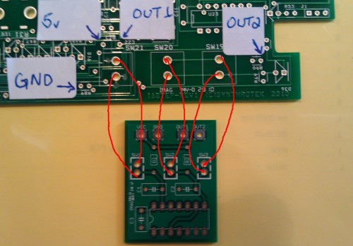
- Rewire switches
- Leaving the switches on the board attach wires on the bottom side and connect to MOD board as shown
Step 5
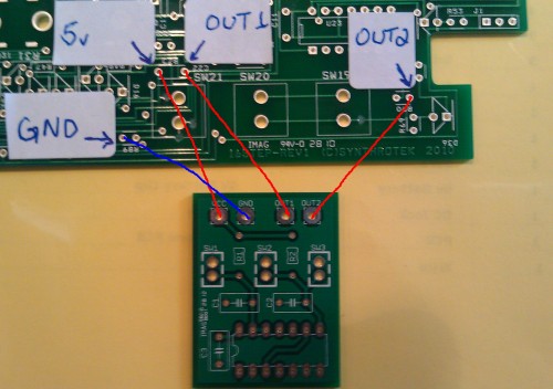
- Wire VCC, GND, OUT1 and OUT2
- VCC (5v) connects to the left side of C28
- GND connects to left side of R89
- OUT1 connects to right side of C28
- OUT2 connects to right side of R90
- Remember you removed these components (step 1), so you can insert the wires directly into the holes indicated. DO NOT add the capacitors and resistors back into these positions. The parts on the MOD board will now be doing the work of the removed components.
- If you do this step by inserting the wire from the bottom side of the 16 Step board and then solder on the top side you will be able to hide the mod board under the 16 Step board.
Step 6
- Enjoy!
A few additional points about the 16 Step Synthesizer:
- J1 MUST be a mono jack with shunt (stereo jacks will cause the board to malfunction)
- J1 is wired Sleeve, Ring, Tip from left to right
- SW22 is not required. Top two holes on the left side can be shorted together, and top two holes on the right can be shorted together
If you have any questions, do not hesitate to contact us.


I have an unbuilt 16 step kit including the MOD PCB.
What does the MOD PCB do ?, and, is it required ?.
Hi Cliff, it fixes a bounce to switch problem. It really is helpful. Otherwise the step through push-button momentary switch skips steps as you are moving through them.