Important Links
Product Page
Store Page
Assembly Instructions
Bill of Materials
Schematic
Capacitor and Resistor Lookup Guide
Welcome to the 555 Timer Assembly Instruction! This simple circuit is very powerful and has a ton of applications. Let’s get started!
Component Layout
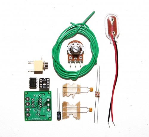
Check to make sure that you have all of the components included in the kit. Not only will this help you finish the circuit, but it will familiarize you with each component.
For these instructions, a DC jack is used. However, this component is not necessary to power your circuit and it is not included in kits.
Alright, let’s get started building!
Assembly
Attention: Changes may occur after the Assembly Instructions are created and the photos may not reflect those changes. Always use the BOM to verify the placement of components.
On-board Components
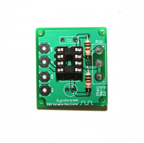
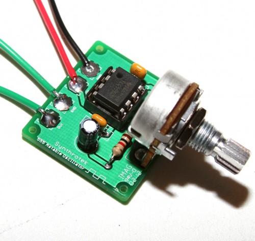
Insert the IC Socket, and the 1k resistors into the PCB. Use the picture above for a reference.
Bend the leads on the back, and solder the components into place. Then clip the leads!
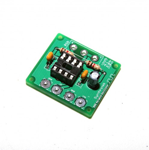
The capacitors are placed as shown. C1 is a polarized electrolytic capacitor, and it’s lead placement is important. The colored stripe on the side of the electrolytic capacitor denotes the negative lead. Place the shorter negative lead into the circle through-hole, and the longer lead into the square (positive) through-hole. C2 and C3 are ceramic capacitors; their placement does not matter.
My personal preference is to insert multiple components before any soldering takes place. Make sure your soldering joints are clean before you clip any leads from the capacitors or the resistor.
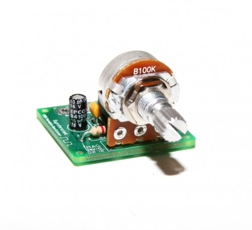
Insert the potentiometer as shown in the picture above, and solder the pin-connections.
The potentiometer can also be wired. Just make sure to align it in the same way.
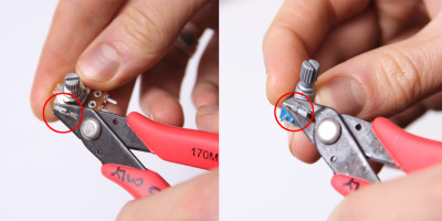
When installing the pot, some pots come with nubs near the shaft that may get in the way of installing the circuit into a case. Check for a nub and clip as necessary.
Wired Components
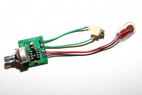
The remaining components of the 555 Timer circuit are attached to the PCB via wires. Use longer wires than you need when soldering to the component. Wire can always be cut; desoldering short wires and resoldering new wires to the PCB and component is a very frustrating error that can be avoided.
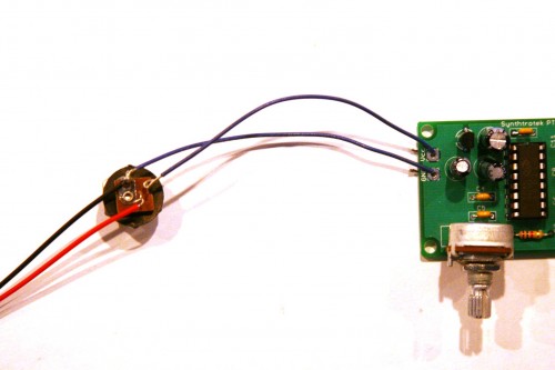
The jacks are very easy to solder to the board.
The red wire of the battery jack goes to the V+ PCB position and the black wire goes to the GND position.
If you are using a DC jack with your circuit, read on.
These are pictures from the Synthrotek Dev Board Assembly Instructions. They will explain how to wire up a 9volt DC jack along with the battery jack for your 555 timer.
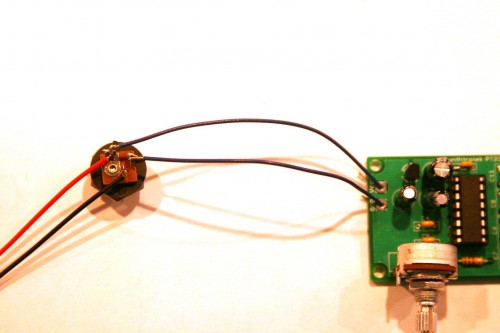
Use this picture for wiring a center positive power supply. The red and black wires are the battery jack connections.
The top through-hole on the PCB where the DC jack is connected reads “Vcc” which is the same as V+ on the 555 PCB.
The through-hole below that is the GND. Wire up the 555 Timer PCB in the same manner.
Use this picture for wiring a center negative power supply. The red and black wires are the battery jack connections.
Mods/Applications
If you are new to electronics, you may not fully understand the point of this circuit. That’s totally OK and we are going to show you what you can do with it. There’s more to it than just flashing an LED on and off!
The circuit layout is for a 555 timer in astable mode. Basically, this means that you will have a continuous transition from a high voltage level (determined by and slightly less than your supply voltage) to 0V at a certain frequency (number of times per second). In digital circuits, this is known as a clock pulse and is very important for timing or triggering events. In fact, our 8/10 step sequencer and 16 step sequencer both utilize an astable 555 timer circuit!
For more info, check out this link. They do a great job of explaining the circuit as well as showing how to calculate frequency and component values.
Controlling a Relay
CV Input
Circuit Bending


Any chance you could put some content under the CV Input and Circuit Bending headlines at the bottom of the page? I just built this and It’d be interesting to learn how to do those things. or maybe point me towards a good resource with info that’s compatible with this particular circuit
hey man, sorry, we haven’t had the time to really dig into this circuit like i’d like to. I know the 555 timer circuit is a pretty popular one, and lots of people use them in circuit bending. I’ve heard Casperelectronics.com is a good resource for bending, though I don’t know if he has any 555 timer specific stuff on there.
Cool. Yeah I’ve found a lot of resources online, I think I just need to learn a little more about what I’m doing before I can make use of them. In any case, it works and it’s easy to make!
Hello all,
I’ve put my 555 timer kit together but when i plug it in I get no output. Im a novice at this so im not sure how to trouble shoot at this point. I did make some changes to the build such as changing out the 1/4″ jack for a 1/8″ one and I have wired the adjustable potentiometer and instead of the battery jack I have a D/C jack in it’s place. That being said everything looks ok to my novice eye.
Any help would be greatly appreciated.
Regards
Steve
Hey Steve,
First thing I would check is that the parts are all in the proper spot as per the BOM, and maybe give the Troubleshooting Guide a look over.
If that doesn’t produce any results, the next step would be to take a multi-meter and just follow the voltage, starting at the DC jack, and make sure its getting everywhere it should.
If you’re still having troubles with it after those steps, just give us a holler over at store@synthrotek.com, and we can get it sorted out.
Best,
-Patrick at Synthrotek
@Patrick Kelly
Thanks Patrick 🙂 will do,,,
hi! i’m looking how to conect mi 555 timer to mi 2399 delay on pin 6 as shown on the videos. it that easy to explane or have you some link or tuto for me?
For more ideas and circuits on 555 timers try searching for a not in print book “555 Timer Cookbook by Forest M. Mims” or the Nuts and Volts Magazine at https://www.nutsvolts.com/