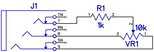
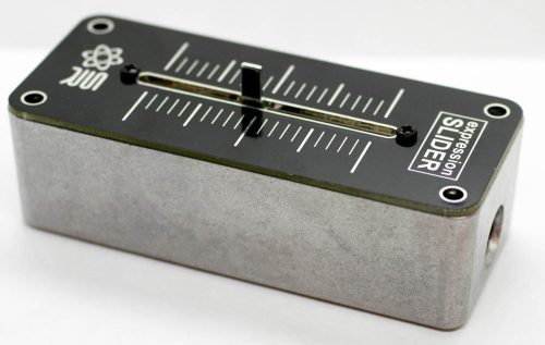
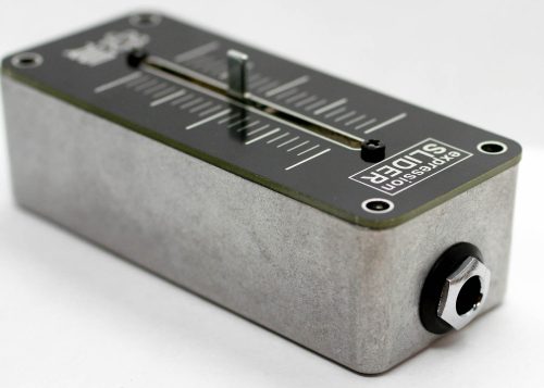
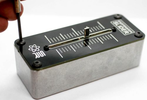
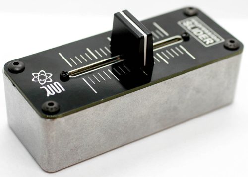
Thank you for purchasing the Synthrotek Expression Slider Kit! This is a fairly easy project, but please get help from a friend if you need it BEFORE starting!
ATTN: Please follow the BOM and these instructions. Don’t populate from the PCB silkscreen or these instruction pictures alone. Our components may look different from the pictures, so please look over your parts and check the codes first.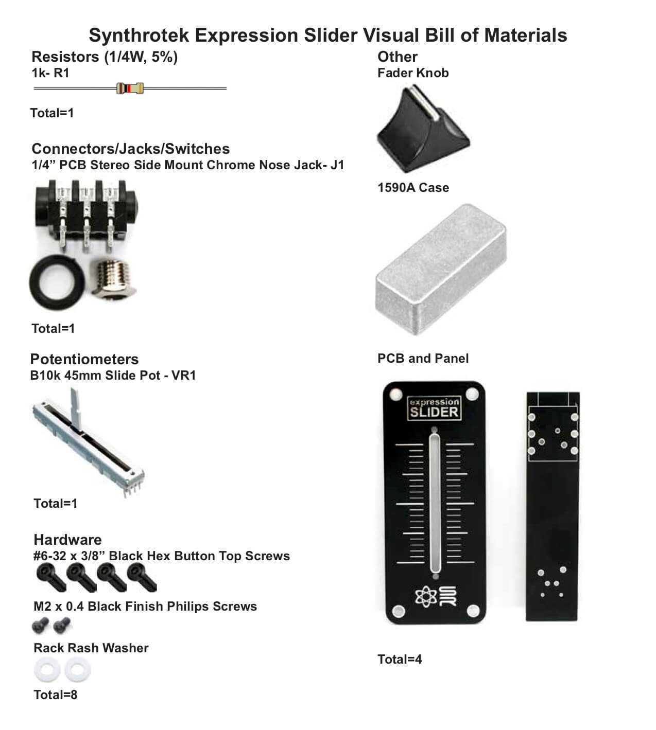 For a BOM with Mouser part numbers, click here.
RESISTOR
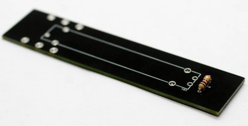
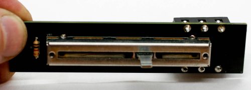
Place the resistor into the PCB as shown below. Resistors are non-polarized components, so you can place it either direction. Carefully turn over to solder then clip excess leads.
SLIDE POTENTIOMETER
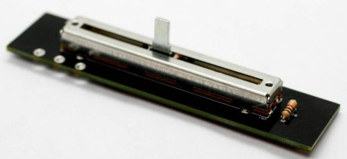
Place the slide potentiometer into the PCB; it will only go in one way. Carefully turn over to solder in place.
STEREO 1/4″ Jack
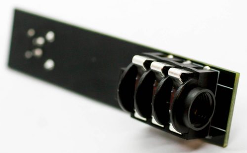
Place the 1/4″ jack into the PCB as shown below. Carefully turn over to solder place.
PANEL PLACEMENT
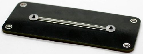
Take the two smaller black screws and place them into the front side of the panel then carefully turn the panel over. Take the two small washers and place them onto the screws.
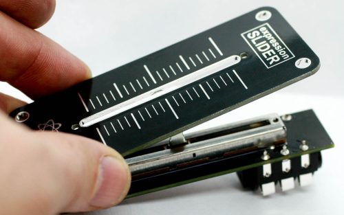
This takes some dexterity! Take the panel with the screws and washers and place it on top of the PCB and screw the screws into the slide pot.
Next, take the recessed nut and screw it into the stereo jack through the case.
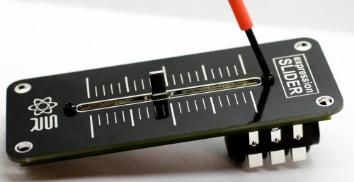
Finally screw in the four black hex-head screws into the four mounting holes into the case.
You can finish up your project by placing the slider knob onto the slider shaft as shown below!


