


This product has been discontinued.
Looking for Parts?
- CD4046 Phase-Locked Loop IC
- MN3207 Long Delay IC
- TL062 OpAmp IC
- 9mm Vertical Potentiometer – 100K Linear
- 9mm Vertical Potentiometer – 100K Audio
- 1/4″ Mono Audio Jacks – PCB Mounted
- 1/4″ Stereo Audio Jacks – PCB Mounted
- 3PDT Guitar Pedal Stomp Switch
- 1590B Pre-drilled case for Guitar Pedals
Welcome to the Synthrotek Chorus Pedal assembly instructions. This will walk you through assembling your Chorus Pedal.
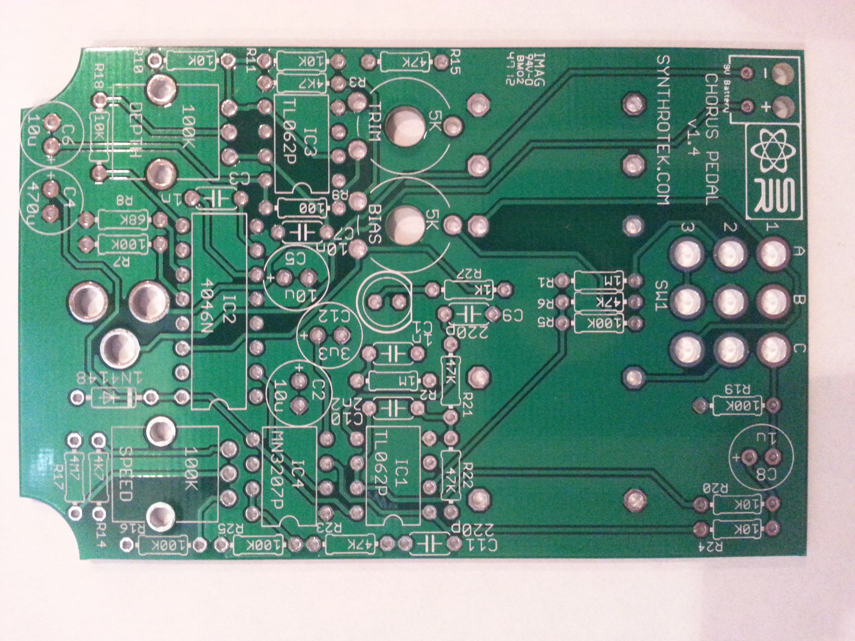
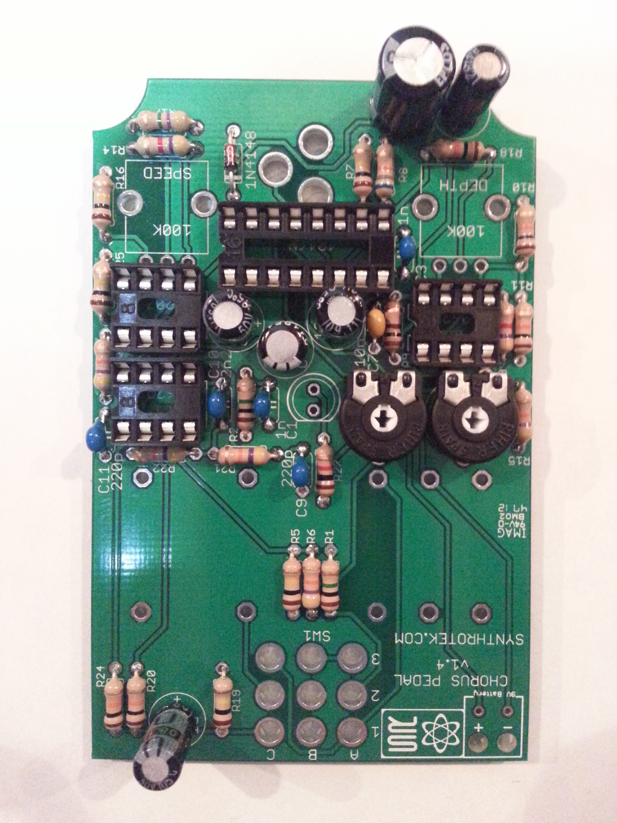
Component Layout
The first step is to ensure you have all the parts needed. Check the contents of your kit against the BOM before you begin. If you are missing anything send us an e-mail and we’ll send it off to you ASAP. Familurize yourself with the PCB and which components will go where.
Assembly
Attention: Changes may occur after the Assembly Instructions are created and the photos may not reflect those changes. Always use the BOM to verify the placement of components.
First we will apply the smaller components to the board. Applying the larger components first will make applying some of the smaller components difficult.
Resistors And Diode
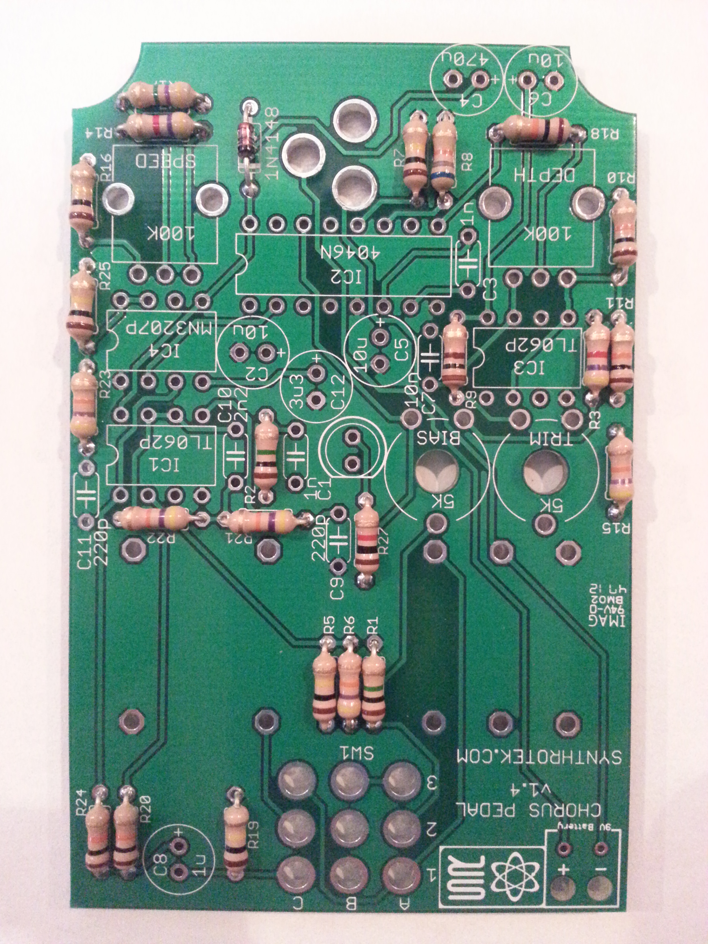
Insert the resistors and the diode into their corrisponding PCB locations according to the BOM and solder them to the board. Resistors are not polar components and are not fragile, so don’t worry about damaging them with the Soldering Iron.
The diode (1N4148) is a polar component and the darker line around one end should match the symbol on the PCB. Make sure you insert the diode in the correct manner or else your Chorus Pedal will not function correctly.
IC Sockets
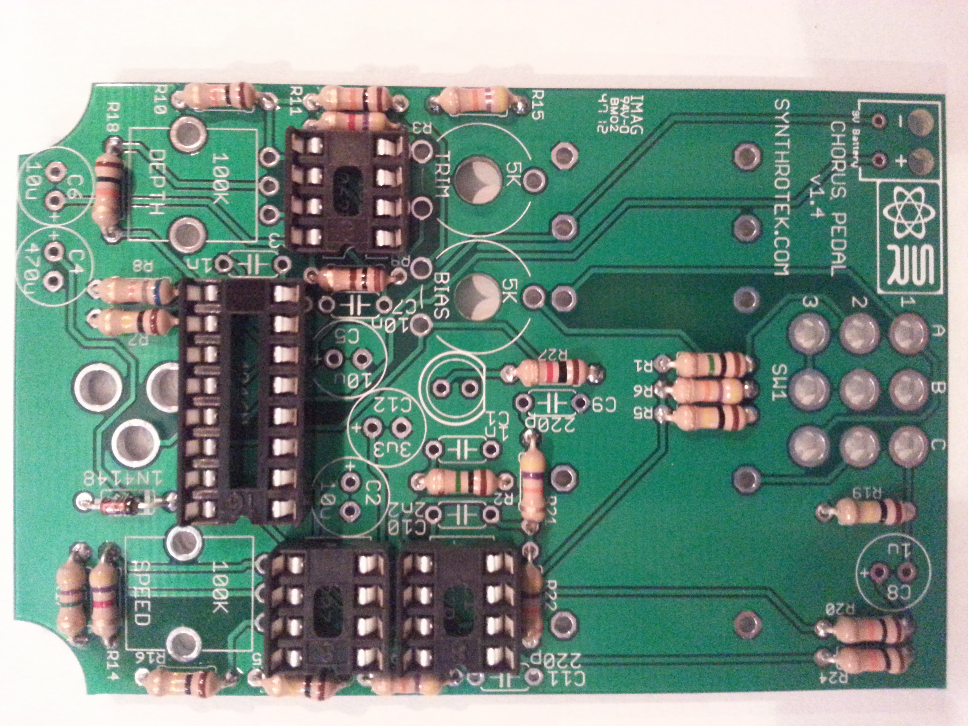
The IC Sockets are next. Insert the IC sockets into the PCB with the notch on the IC socket matching the IC socket outline on the PCB. The notch will indicate pin placement when you install the IC. Because ICs are sensitive components wait until later to insert the ICs into their sockets.
Trim Potentiometers
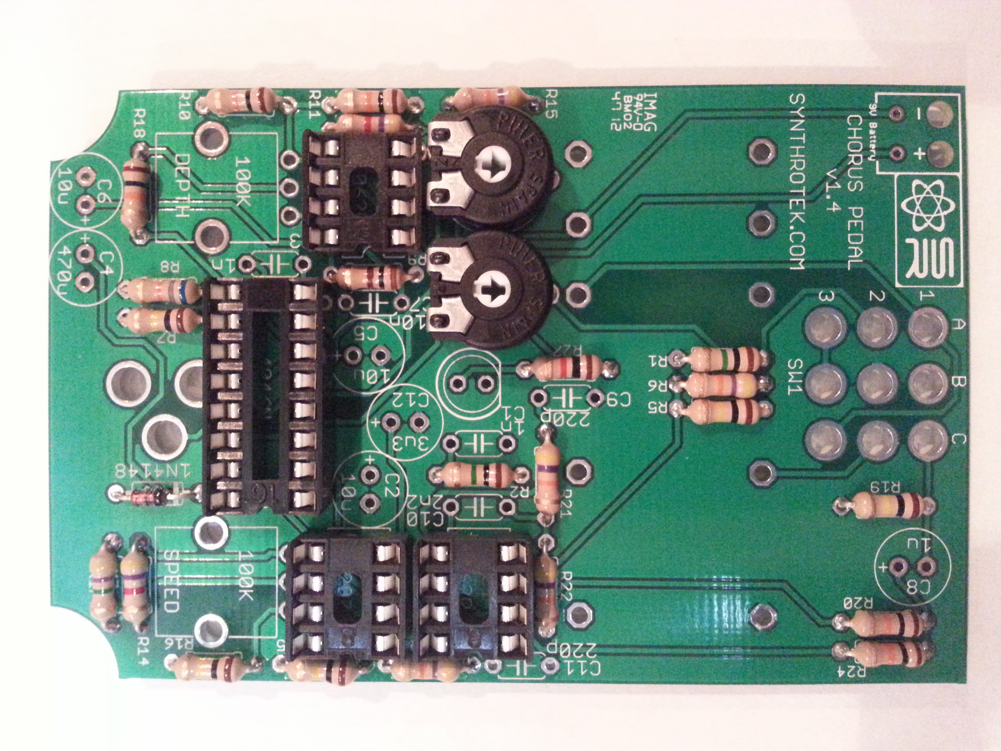 Insert both trim pots into the PCB and solder them in place.
Capacitors
Next up insert the capacitors.There are two types of capacitors used, electrolytic and ceramic capacitors. The electrolytic capacitors (C2, C4, C5, C6, C8, and C12) are polar components and must be inserted in the correct orientation. The longer lead will be the positive end. Ensure that the positive end goes into the hole marked with a positive sign (+). The ceramic capacitors (C1, C3, C7, C9, C10, C11) are not polar components and can be inserted in any direction.
Power Supply
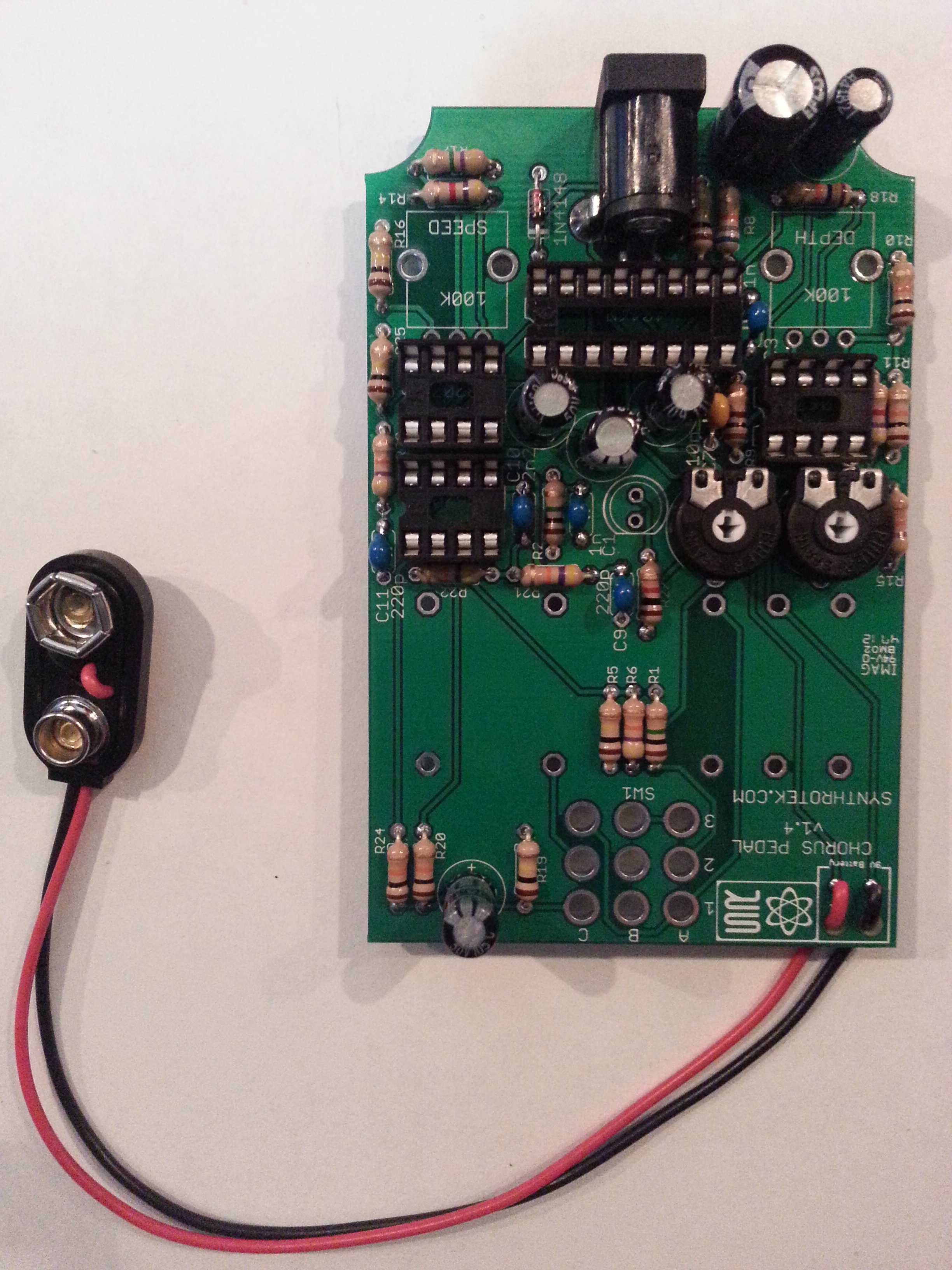
Now we want to insert where you will hook up your power supply. The DC jack goes into the set of three large holes near the top of the PCB. For the 9v battery clip insert the red wire through the hole marked with the ‘+’ and the black wire through the hole marked with the ‘-‘.
Potentiometers and Input/Output
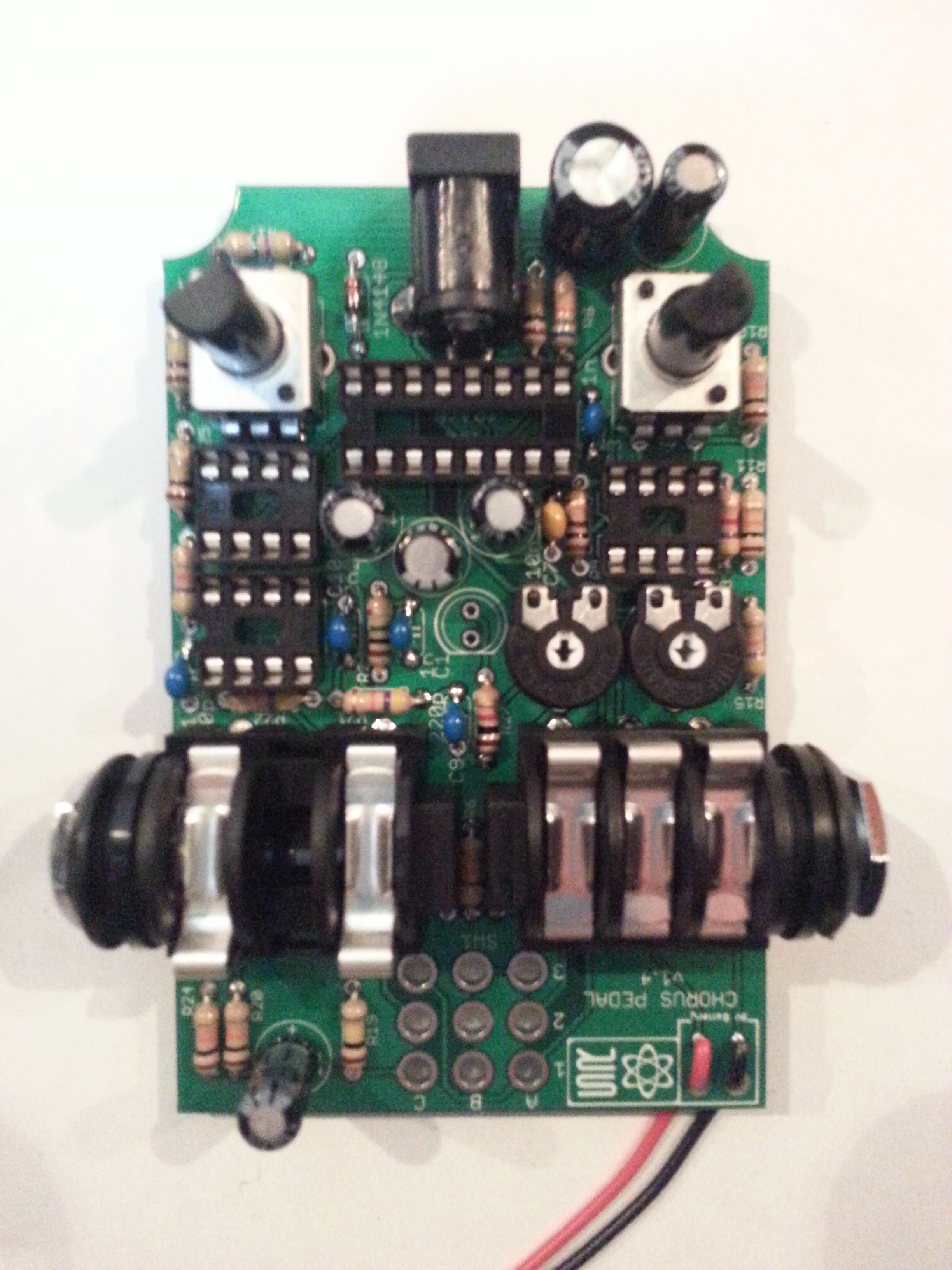
Now insert the two potentiometers and the input/output jacks. If you have your PCB oriented like in the image above the mono 1/4″ jack goes on the left-hand side of the board and the stereo 1/4″ jacks goes on the right-hand side of the board.
When installing the pot, some pots come with nubs near the shaft that may get in the way of installing the circuit into a case. Check for a nub and clip as necessary.

Don’t forget to cut the nubs on the potentiometers as neccesary.
LED and Stomp Switch

We’re almost done! Now it’s time to insert the LED and the stomp switch. Both of these components need to be inserted in the correct orientation or else the LED will not function and the stomp switch won’t fit. For the LED, the short lead on the LED is the LED’s flat side. Make sure you insert the LED with it’s flat side matching the flat side on the PCB’s silk screen.
As for the stomp switch, the sides of the stomp switch’s body that is all blue plastic should be facing to the top/bottom of the PCB while the sides that have the metal top wrapped down the sides should be facing to the left/right of the PCB. If you do not have it oriented correctly the pins will not match up with the holes on the PCB.
Now you will want to insert the ICs into their sockets. Ensure that either the notch or the dot on the top of the IC is towards the end of the socket that has a notch on it. Inserting it backwards may damage your IC.
And now you’re done! Enjoy your completed Chorus Pedal.
9 Comments